HP Cluster Platform Interconnects v2010 HP Cluster Platform InfiniBand Interco - Page 86
Cabling Tables, 7.1.3 Connecting InfiniBand Cables
 |
View all HP Cluster Platform Interconnects v2010 manuals
Add to My Manuals
Save this manual to your list of manuals |
Page 86 highlights
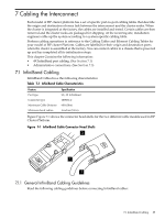
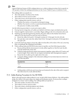
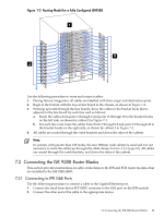
Caution: Do not bend the InfiniBand cables too sharply. The minimum bend radius is 4" (10 cm). • Follow the cabling procedure to avoid creating airflow dams, particularly for the ISR 9024, which employs passive cooling. • Consider the requirements and constraints of the installation location. For example, if cooling air is supplied through floor vents, avoid covering the vents. Avoid air leaks into cable conduits by using the appropriate seals or baffles. • Use appropriate gaskets and cable protection where cables pass through metal openings. Do not allow sharp metal edges to abrade or cut the cable cladding. • Do not kink the cable. • Do not twist the connector. 7.1.2 Cabling Tables The following documents provide cabling tables for supported InfiniBand configurations: • InfiniBand 1U Server 2:1 Reduced Bandwidth Cabling Tables • InfiniBand 1U Server Full Bandwidth Cabling Tables • InfiniBand 2U Server 2:1 Reduced Bandwidth Cabling Tables • InfiniBand 2U Server Full Bandwidth Cabling Tables • InfiniBand 4U Server 2:1 Reduced Bandwidth Cabling Tables • InfiniBand 4U Server Full Bandwidth Cabling Tables You can find these documents on the following Web site:http://docs.hp.com, under the heading High Performance Computing. 7.1.3 Connecting InfiniBand Cables Use the following procedure to connect an InfiniBand cable: 1. Align the InfiniBand cable connector with the port on a line board. 2. Depending on the type of cable in use: • Squeeze the tabs on either side of the head shell (see callout 1 in Figure 7-1) and push the connector onto the port, releasing the tabs to lock the head shell in place • Pull back the locking handle on the head shell (see callout 2 in Figure 7-1) and push the connector onto the port by holding the head shell body (not the handle). Push in the handle to lock the head shell in place. 3. Pull gently on the head shell (never on the cable) to ensure that the connector has locked in place. 4. Route the cable to the nearest cabling guide hook, in accordance with the cable routing procedure for your model of Cluster Platform. 5. Verify that the Link State green LED illuminates and does not flash. This indicates a good physical connection. See Chapter 9 if the LED does not illuminate. 7.1.4 Cable Routing Procedure for the ISR 9024 or ISR 9024 S/D Refer to the appropriate cabling tables for your model of HP Cluster Platform. The cabling tables define the syntax of the port names for origin and destination ports. Every port has a unique designator to ensure correct cabling. 86 Cabling the Interconnect
-
 1
1 -
2
-
3
-
4
-
5
-
6
-
7
-
8
-
9
-
10
-
11
-
12
-
13
-
14
-
15
-
16
-
17
-
18
-
19
-
20
-
21
-
22
-
23
-
24
-
25
-
26
-
27
-
28
-
29
-
30
-
31
-
32
-
33
-
34
-
35
-
36
-
37
-
38
-
39
-
40
-
41
-
42
-
43
-
44
-
45
-
46
-
47
-
48
-
49
-
50
-
51
-
52
-
53
-
54
-
55
-
56
-
57
-
58
-
59
-
60
-
61
-
62
-
63
-
64
-
65
-
66
-
67
-
68
-
69
-
70
-
71
-
72
-
73
-
74
-
75
-
76
-
77
-
78
-
79
-
80
-
 81
81 -
 82
82 -
 83
83 -
 84
84 -
 85
85 -
 86
86 -
 87
87 -
 88
88 -
 89
89 -
 90
90 -
 91
91 -
92
-
93
-
94
-
95
-
96
-
97
-
98
-
99
-
100
-
101
-
102
-
103
-
104
-
105
-
106
-
107
-
108
-
109
-
110
-
111
-
112
-
113
-
114
-
115
-
116
-
117
-
118
-
119
-
120
-
121
-
122
-
123
-
124
-
125
-
126
-
127
-
128
-
129
-
130
-
131
-
132
-
133
-
134
-
135
-
136
-
137
-
138
-
139
-
140
 |
 |
