HP Cluster Platform Interconnects v2010 HP Cluster Platform InfiniBand Interco - Page 73
Installing or Replacing sLB-24 Line Boards, Table 6-1 sFB-12 Fabric Board LED Status
 |
View all HP Cluster Platform Interconnects v2010 manuals
Add to My Manuals
Save this manual to your list of manuals |
Page 73 highlights
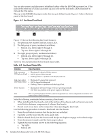
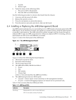
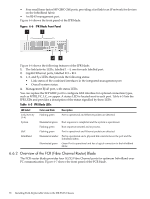
Table 6-1 sFB-12 Fabric Board LED Status Indication Link Description Each pair of LEDs indicates the status of six ports of each line board. The two LEDs in each pair are: • Green - The physical link is up when this LED is illuminated. • Amber - The logical link is up when this LED is illuminated. Possible alternate states are: • LED not illuminated - No link is detected on any of the line board's 6 ports (line board missing) • LED flashing - Only some of the ports have a link (line board is possibly faulty). Power (Green) Hot Swap (Blue) Info Illuminated - All board voltage levels are operating normally. Not illuminated - There is a problem with the power supply to the board. Illuminated - You can remove the board. Not illuminated - You cannot remove the board. This is a general purpose LED for system management use. Various diagnostic procedures will instruct you to check its status. Note the following constraints before inserting a fabric board: • Use caution when inserting the fabric board on the extreme left-hand side of the chassis. There is a very narrow clearance between the board components and the chassis case. • Use caution when inserting fabric boards because the ejectors can break when you lock them in place. Always lock the ejectors in place gently. • When sliding in the board, do so by pushing at the center of the board front panel and not by pushing on the ejectors. Use the following procedure to insert a fabric board to the chassis: 1. Verify that the ejectors are unlocked by pressing the red button. 2. Carefully seat the board into the side guide rails. 3. Slowly slide the board into the chassis until the ejectors begin to engage on the chassis edge. 4. Verify that the front panel of the fabric board is completely vertical and the board's bezel is flush with the front panel of the chassis. 5. Press the ejectors gently inwards until the locks snap into place. 6. Tighten the four security screws in the following sequence: a. Top right. b. Bottom left. c. Top left. d. Bottom right. 7. Verify the status of the following LEDs: a. The power LED is illuminated. b. The info LED is not illuminated. Use the following procedure to extract a fabric board from the chassis: 1. Disconnect all cables. 2. Release the security screws. 3. Press the red buttons to unlock the ejectors. 4. Wait for the blue hot swap LED to illuminate. 5. Press the ejectors outwards and slowly slide out the board. 6.3 Installing or Replacing sLB-24 Line Boards You can install or replace ISR 9288 line boards without interfering with data traffic or with the operation of adjacent line boards, even when the ISR 9288 is fully populated with line boards. 6.3 Installing or Replacing sLB-24 Line Boards 73
-
 1
1 -
2
-
3
-
4
-
5
-
6
-
7
-
8
-
9
-
10
-
11
-
12
-
13
-
14
-
15
-
16
-
17
-
18
-
19
-
20
-
21
-
22
-
23
-
24
-
25
-
26
-
27
-
28
-
29
-
30
-
31
-
32
-
33
-
34
-
35
-
36
-
37
-
38
-
39
-
40
-
41
-
42
-
43
-
44
-
45
-
46
-
47
-
48
-
49
-
50
-
51
-
52
-
53
-
54
-
55
-
56
-
57
-
58
-
59
-
60
-
61
-
62
-
63
-
64
-
65
-
66
-
67
-
 68
68 -
 69
69 -
 70
70 -
 71
71 -
 72
72 -
 73
73 -
 74
74 -
 75
75 -
 76
76 -
 77
77 -
 78
78 -
79
-
80
-
81
-
82
-
83
-
84
-
85
-
86
-
87
-
88
-
89
-
90
-
91
-
92
-
93
-
94
-
95
-
96
-
97
-
98
-
99
-
100
-
101
-
102
-
103
-
104
-
105
-
106
-
107
-
108
-
109
-
110
-
111
-
112
-
113
-
114
-
115
-
116
-
117
-
118
-
119
-
120
-
121
-
122
-
123
-
124
-
125
-
126
-
127
-
128
-
129
-
130
-
131
-
132
-
133
-
134
-
135
-
136
-
137
-
138
-
139
-
140
 |
 |
