HP ProLiant DL170e HP ProLiant DL170e G6 Server Maintenance and Service Guide - Page 148
Power bus bar system
 |
View all HP ProLiant DL170e manuals
Add to My Manuals
Save this manual to your list of manuals |
Page 148 highlights
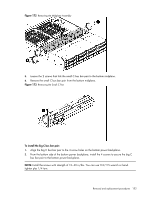
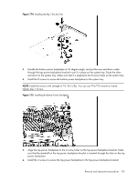
Power bus bar system The HP ProLiant DL170e G6 server uses the copper power bus bar system for power transferring, which efficiently reduces the power loss during the power transferring process from the power supply units to the system boards. The power bus bar link system consists of the following elements: • Big C bus bar pair: Transfer power from the bottom power backplane to the top power backplane • Bus bar links: Transfer power from the top power backplane to the top midplane • Small C bus bar pair: Transfer power from the top midplane to the bottom midplane The following figure shows the power bus bar link system structure with reference to the top/bottom power backplanes and top/bottom midplanes: Figure 165 Power Bus Bar Link System Structure Item 1 2 3 Description Small C bus bar pair (between the top midplane and the bottom midplane) Bus bar links (between the top midplane and the top power backplane) Big C bus bar pair (between the top power backplane and the bottom power backplane) To remove the bus bar links: Before removing the bus bar links, take steps as described in the section of "Pre-installation procedure". 1. Remove the power supply units as described in the section of "To remove the power supply". 2. Press the semi-circle shaped end of the plastic bus bar cover to release the bus bar cover from the midplane assembly. 3. Route up the semi-circle shaped end of the plastic bus bar cover and remove it from the hood bracket. Removal and replacement procedures 148
-
 1
1 -
2
-
3
-
4
-
5
-
6
-
7
-
8
-
9
-
10
-
11
-
12
-
13
-
14
-
15
-
16
-
17
-
18
-
19
-
20
-
21
-
22
-
23
-
24
-
25
-
26
-
27
-
28
-
29
-
30
-
31
-
32
-
33
-
34
-
35
-
36
-
37
-
38
-
39
-
40
-
41
-
42
-
43
-
44
-
45
-
46
-
47
-
48
-
49
-
50
-
51
-
52
-
53
-
54
-
55
-
56
-
57
-
58
-
59
-
60
-
61
-
62
-
63
-
64
-
65
-
66
-
67
-
68
-
69
-
70
-
71
-
72
-
73
-
74
-
75
-
76
-
77
-
78
-
79
-
80
-
81
-
82
-
83
-
84
-
85
-
86
-
87
-
88
-
89
-
90
-
91
-
92
-
93
-
94
-
95
-
96
-
97
-
98
-
99
-
100
-
101
-
102
-
103
-
104
-
105
-
106
-
107
-
108
-
109
-
110
-
111
-
112
-
113
-
114
-
115
-
116
-
117
-
118
-
119
-
120
-
121
-
122
-
123
-
124
-
125
-
126
-
127
-
128
-
129
-
130
-
131
-
132
-
133
-
134
-
135
-
136
-
137
-
138
-
139
-
140
-
141
-
142
-
 143
143 -
 144
144 -
 145
145 -
 146
146 -
 147
147 -
 148
148 -
 149
149 -
 150
150 -
 151
151 -
 152
152 -
 153
153 -
154
-
155
-
156
-
157
-
158
-
159
-
160
-
161
-
162
-
163
-
164
-
165
-
166
-
167
-
168
-
169
-
170
-
171
-
172
-
173
-
174
-
175
-
176
-
177
-
178
-
179
-
180
 |
 |
