HP ProLiant DL170e HP ProLiant DL170e G6 Server Maintenance and Service Guide - Page 162
Connectors, switches, and LEDs, Connectors and components, Front panel components
 |
View all HP ProLiant DL170e manuals
Add to My Manuals
Save this manual to your list of manuals |
Page 162 highlights
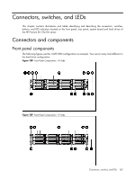
Connectors, switches, and LEDs This chapter contains illustrations and tables identifying and describing the connectors, switches, buttons, and LED indicators located on the front panel, rear panel, system board and hard drives of the HP ProLiant DL170e G6 server. Connectors and components Front panel components The following figures use the 12-LFF-HDD configuration as example. Your server many look different in the hard drive configuration. Figure 188 Front Panel Components / 4 Node Figure 189 Front Panel Components / 2 Node Connectors, switches, and LEDs 162
-
 1
1 -
2
-
3
-
4
-
5
-
6
-
7
-
8
-
9
-
10
-
11
-
12
-
13
-
14
-
15
-
16
-
17
-
18
-
19
-
20
-
21
-
22
-
23
-
24
-
25
-
26
-
27
-
28
-
29
-
30
-
31
-
32
-
33
-
34
-
35
-
36
-
37
-
38
-
39
-
40
-
41
-
42
-
43
-
44
-
45
-
46
-
47
-
48
-
49
-
50
-
51
-
52
-
53
-
54
-
55
-
56
-
57
-
58
-
59
-
60
-
61
-
62
-
63
-
64
-
65
-
66
-
67
-
68
-
69
-
70
-
71
-
72
-
73
-
74
-
75
-
76
-
77
-
78
-
79
-
80
-
81
-
82
-
83
-
84
-
85
-
86
-
87
-
88
-
89
-
90
-
91
-
92
-
93
-
94
-
95
-
96
-
97
-
98
-
99
-
100
-
101
-
102
-
103
-
104
-
105
-
106
-
107
-
108
-
109
-
110
-
111
-
112
-
113
-
114
-
115
-
116
-
117
-
118
-
119
-
120
-
121
-
122
-
123
-
124
-
125
-
126
-
127
-
128
-
129
-
130
-
131
-
132
-
133
-
134
-
135
-
136
-
137
-
138
-
139
-
140
-
141
-
142
-
143
-
144
-
145
-
146
-
147
-
148
-
149
-
150
-
151
-
152
-
153
-
154
-
155
-
156
-
 157
157 -
 158
158 -
 159
159 -
 160
160 -
 161
161 -
 162
162 -
 163
163 -
 164
164 -
 165
165 -
 166
166 -
 167
167 -
168
-
169
-
170
-
171
-
172
-
173
-
174
-
175
-
176
-
177
-
178
-
179
-
180
 |
 |

Connectors, switches, and LEDs
162
Connectors, switches, and LEDs
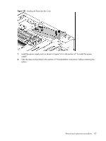
This chapter contains illustrations and tables identifying and describing the connectors, switches,
buttons, and LED indicators located on the front panel, rear panel, system board and hard drives of
the HP ProLiant DL170e G6 server.
Connectors and components
Front panel components
The following figures use the 12-LFF-HDD configuration as example. Your server many look different in
the hard drive configuration.
Figure 188
Front Panel Components / 4 Node
Figure 189
Front Panel Components / 2 Node