HP ProLiant DL170e HP ProLiant DL170e G6 Server Maintenance and Service Guide - Page 155
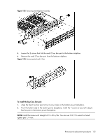
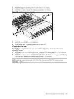
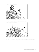
Install the 6 screws to secure and link the bus bar links to the top power backplane and the big
 |
View all HP ProLiant DL170e manuals
Add to My Manuals
Save this manual to your list of manuals |
Page 155 highlights
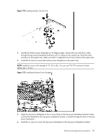
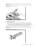
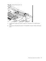
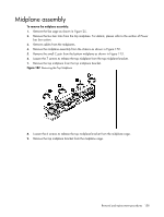
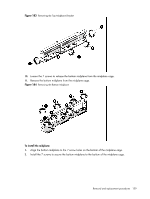
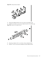
3. Align the midplane assembly to the 4 screw holes on the chassis. 4. Install the 4 screws to secure the midplane assembly to the chassis. Figure 178 Installing the Midplane Assembly 5. Install all removed cables to the midplanes. 6. Install the fan cage. For details, please refer to Figure 27. To install the bus bar links: After the big C and small C bus bar pairs are installed in the chassis, the bus bar links can be installed as follows: 1. Align the bus bar links to the 6 screw holes on the top power backplane and the top midplane. 2. Install the 6 screws to secure and link the bus bar links to the top power backplane (and the big C bus bar pair) and the top midplane (and the small C bus bar pair). NOTE: Install the screws with strength of 10~30 in/lbs. You can use T10/T15 wrench or handtighten plus 1/4 turn. Removal and replacement procedures 155
-
 1
1 -
2
-
3
-
4
-
5
-
6
-
7
-
8
-
9
-
10
-
11
-
12
-
13
-
14
-
15
-
16
-
17
-
18
-
19
-
20
-
21
-
22
-
23
-
24
-
25
-
26
-
27
-
28
-
29
-
30
-
31
-
32
-
33
-
34
-
35
-
36
-
37
-
38
-
39
-
40
-
41
-
42
-
43
-
44
-
45
-
46
-
47
-
48
-
49
-
50
-
51
-
52
-
53
-
54
-
55
-
56
-
57
-
58
-
59
-
60
-
61
-
62
-
63
-
64
-
65
-
66
-
67
-
68
-
69
-
70
-
71
-
72
-
73
-
74
-
75
-
76
-
77
-
78
-
79
-
80
-
81
-
82
-
83
-
84
-
85
-
86
-
87
-
88
-
89
-
90
-
91
-
92
-
93
-
94
-
95
-
96
-
97
-
98
-
99
-
100
-
101
-
102
-
103
-
104
-
105
-
106
-
107
-
108
-
109
-
110
-
111
-
112
-
113
-
114
-
115
-
116
-
117
-
118
-
119
-
120
-
121
-
122
-
123
-
124
-
125
-
126
-
127
-
128
-
129
-
130
-
131
-
132
-
133
-
134
-
135
-
136
-
137
-
138
-
139
-
140
-
141
-
142
-
143
-
144
-
145
-
146
-
147
-
148
-
149
-
 150
150 -
 151
151 -
 152
152 -
 153
153 -
 154
154 -
 155
155 -
 156
156 -
 157
157 -
 158
158 -
 159
159 -
 160
160 -
161
-
162
-
163
-
164
-
165
-
166
-
167
-
168
-
169
-
170
-
171
-
172
-
173
-
174
-
175
-
176
-
177
-
178
-
179
-
180
 |
 |
