HP ProLiant DL170e HP ProLiant DL170e G6 Server Maintenance and Service Guide - Page 154
Removal and replacement procedures, Installing the Top Power Backplane
 |
View all HP ProLiant DL170e manuals
Add to My Manuals
Save this manual to your list of manuals |
Page 154 highlights
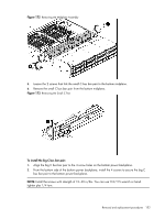
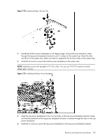
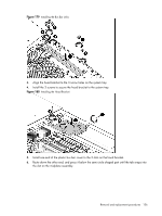
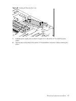
NOTE: Install the screws with strength of 10~30 in/lbs. You can use T10/T15 wrench or handtighten plus 1/4 turn. Figure 176 Installing the Top Power Backplane 7. Install all removed cables to the power backplanes. To install the small C bus bar pair: 1. Align the small C pair to the 2 screw holes on the bottom midplane and the top midplane. 2. From the outside of the bottom of the midplane cage, put the 2 screws through the screw holes on the midplane cage, the bottom midplane and the small C bus bar pair. Install the 2 screws to link and secure the small C bus bar pair to the bottom midplane and the midplane cage. NOTE: Install the screws with strength of 10~30 in/lbs. You can use T10/T15 wrench or handtighten plus 1/4 turn. Figure 177 Installing the Small C Bus Bar Pair Removal and replacement procedures 154
-
 1
1 -
2
-
3
-
4
-
5
-
6
-
7
-
8
-
9
-
10
-
11
-
12
-
13
-
14
-
15
-
16
-
17
-
18
-
19
-
20
-
21
-
22
-
23
-
24
-
25
-
26
-
27
-
28
-
29
-
30
-
31
-
32
-
33
-
34
-
35
-
36
-
37
-
38
-
39
-
40
-
41
-
42
-
43
-
44
-
45
-
46
-
47
-
48
-
49
-
50
-
51
-
52
-
53
-
54
-
55
-
56
-
57
-
58
-
59
-
60
-
61
-
62
-
63
-
64
-
65
-
66
-
67
-
68
-
69
-
70
-
71
-
72
-
73
-
74
-
75
-
76
-
77
-
78
-
79
-
80
-
81
-
82
-
83
-
84
-
85
-
86
-
87
-
88
-
89
-
90
-
91
-
92
-
93
-
94
-
95
-
96
-
97
-
98
-
99
-
100
-
101
-
102
-
103
-
104
-
105
-
106
-
107
-
108
-
109
-
110
-
111
-
112
-
113
-
114
-
115
-
116
-
117
-
118
-
119
-
120
-
121
-
122
-
123
-
124
-
125
-
126
-
127
-
128
-
129
-
130
-
131
-
132
-
133
-
134
-
135
-
136
-
137
-
138
-
139
-
140
-
141
-
142
-
143
-
144
-
145
-
146
-
147
-
148
-
 149
149 -
 150
150 -
 151
151 -
 152
152 -
 153
153 -
 154
154 -
 155
155 -
 156
156 -
 157
157 -
 158
158 -
 159
159 -
160
-
161
-
162
-
163
-
164
-
165
-
166
-
167
-
168
-
169
-
170
-
171
-
172
-
173
-
174
-
175
-
176
-
177
-
178
-
179
-
180
 |
 |
