HP ProLiant DL170e HP ProLiant DL170e G6 Server Maintenance and Service Guide - Page 158
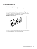
Midplane assembly
 |
View all HP ProLiant DL170e manuals
Add to My Manuals
Save this manual to your list of manuals |
Page 158 highlights
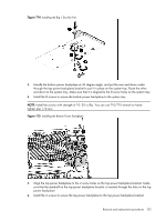
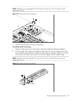
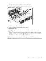
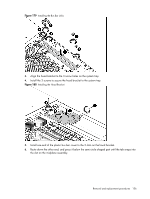
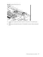
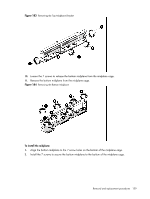
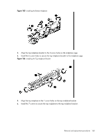
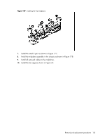
Midplane assembly To remove the midplane assembly: 1. Remove the fan cage as shown in Figure 25. 2. Remove the bus bar links from the top midplane. For details, please refer to the section of Power bus bar system. 3. Remove cables from the midplanes. 4. Remove the midplane assembly from the chassis as shown in Figure 172. 5. Remove the small C pair from the bottom midplane as shown in Figure 173. 6. Loosen the 7 screws to release the top midplane from the top midplane bracket. 7. Remove the top midplane from the top midplane bracket. Figure 182 Removing the Top Midplane 8. Loosen the 6 screws to release the top midplane bracket from the midplane cage. 9. Remove the top midplane bracket from the midplane cage. Removal and replacement procedures 158
-
 1
1 -
2
-
3
-
4
-
5
-
6
-
7
-
8
-
9
-
10
-
11
-
12
-
13
-
14
-
15
-
16
-
17
-
18
-
19
-
20
-
21
-
22
-
23
-
24
-
25
-
26
-
27
-
28
-
29
-
30
-
31
-
32
-
33
-
34
-
35
-
36
-
37
-
38
-
39
-
40
-
41
-
42
-
43
-
44
-
45
-
46
-
47
-
48
-
49
-
50
-
51
-
52
-
53
-
54
-
55
-
56
-
57
-
58
-
59
-
60
-
61
-
62
-
63
-
64
-
65
-
66
-
67
-
68
-
69
-
70
-
71
-
72
-
73
-
74
-
75
-
76
-
77
-
78
-
79
-
80
-
81
-
82
-
83
-
84
-
85
-
86
-
87
-
88
-
89
-
90
-
91
-
92
-
93
-
94
-
95
-
96
-
97
-
98
-
99
-
100
-
101
-
102
-
103
-
104
-
105
-
106
-
107
-
108
-
109
-
110
-
111
-
112
-
113
-
114
-
115
-
116
-
117
-
118
-
119
-
120
-
121
-
122
-
123
-
124
-
125
-
126
-
127
-
128
-
129
-
130
-
131
-
132
-
133
-
134
-
135
-
136
-
137
-
138
-
139
-
140
-
141
-
142
-
143
-
144
-
145
-
146
-
147
-
148
-
149
-
150
-
151
-
152
-
 153
153 -
 154
154 -
 155
155 -
 156
156 -
 157
157 -
 158
158 -
 159
159 -
 160
160 -
 161
161 -
 162
162 -
 163
163 -
164
-
165
-
166
-
167
-
168
-
169
-
170
-
171
-
172
-
173
-
174
-
175
-
176
-
177
-
178
-
179
-
180
 |
 |
