HP ProLiant DL170e HP ProLiant DL170e G6 Server Maintenance and Service Guide - Page 161
Install all removed cables to the midplanes., Install the fan cage as shown
 |
View all HP ProLiant DL170e manuals
Add to My Manuals
Save this manual to your list of manuals |
Page 161 highlights
Figure 187 Installing the Top Midplane 7. Install the small C pair as shown in Figure 177. 8. Install the midplane assembly in the chassis as shown in Figure 178. 9. Install all removed cables to the midplanes. 10. Install the fan cage as shown in Figure 27. Removal and replacement procedures 161
-
 1
1 -
2
-
3
-
4
-
5
-
6
-
7
-
8
-
9
-
10
-
11
-
12
-
13
-
14
-
15
-
16
-
17
-
18
-
19
-
20
-
21
-
22
-
23
-
24
-
25
-
26
-
27
-
28
-
29
-
30
-
31
-
32
-
33
-
34
-
35
-
36
-
37
-
38
-
39
-
40
-
41
-
42
-
43
-
44
-
45
-
46
-
47
-
48
-
49
-
50
-
51
-
52
-
53
-
54
-
55
-
56
-
57
-
58
-
59
-
60
-
61
-
62
-
63
-
64
-
65
-
66
-
67
-
68
-
69
-
70
-
71
-
72
-
73
-
74
-
75
-
76
-
77
-
78
-
79
-
80
-
81
-
82
-
83
-
84
-
85
-
86
-
87
-
88
-
89
-
90
-
91
-
92
-
93
-
94
-
95
-
96
-
97
-
98
-
99
-
100
-
101
-
102
-
103
-
104
-
105
-
106
-
107
-
108
-
109
-
110
-
111
-
112
-
113
-
114
-
115
-
116
-
117
-
118
-
119
-
120
-
121
-
122
-
123
-
124
-
125
-
126
-
127
-
128
-
129
-
130
-
131
-
132
-
133
-
134
-
135
-
136
-
137
-
138
-
139
-
140
-
141
-
142
-
143
-
144
-
145
-
146
-
147
-
148
-
149
-
150
-
151
-
152
-
153
-
154
-
155
-
 156
156 -
 157
157 -
 158
158 -
 159
159 -
 160
160 -
 161
161 -
 162
162 -
 163
163 -
 164
164 -
 165
165 -
 166
166 -
167
-
168
-
169
-
170
-
171
-
172
-
173
-
174
-
175
-
176
-
177
-
178
-
179
-
180
 |
 |

Removal and replacement procedures
161
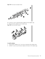
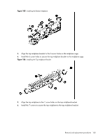
Figure 187
Installing the Top Midplane
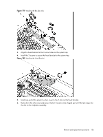
7.
Install the small C pair as shown in Figure 177.
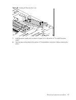
8.
Install the midplane assembly in the chassis as shown in Figure 178.
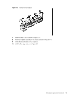
9.
Install all removed cables to the midplanes.
10.
Install the fan cage as shown in Figure 27.