IBM 86884RX Maintenance Manual - Page 147
cover, assembly
 |
View all IBM 86884RX manuals
Add to My Manuals
Save this manual to your list of manuals |
Page 147 highlights
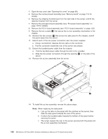
Note: If no devices are selected as active, VGA is used by default. If any device is selected as active, only selected devices are used. You can select multiple devices as active. Hot-plug devices are always active. For instructions to restore a remote-control password, see "Configuring the remote-control password" on page 25. Top cover assembly This section contains instructions for removing and replacing the top cover assembly. Before you begin: v Read "Installation guidelines" on page 77. v Read the safety notices at "Safety notices (multilingual translations)" on page 201. v Read "Handling static-sensitive devices" on page 200. Complete the following steps to remove the top cover assembly. 1. Turn off the server (see "Turning off the server" on page 8), and disconnect all power cords and external cables. 2. Remove the front bezel (see "Removing and replacing the bezel" on page 89). 3. Pull the two retaining pins on the top front of the chassis until they loosen. 4. Slide the top cover to the front slightly. 5. Pull the cover up, and remove it from the server. Retention pins To replace the top cover assembly, complete the following steps: 1. Align the three notches on each side of the cover with the slots in the top of the chassis. 2. Push the cover toward the rear. 3. Push in on the two retaining pins. 4. Replace the front bezel. Chapter 5. Field replaceable units 137
-
 1
1 -
2
-
3
-
4
-
5
-
6
-
7
-
8
-
9
-
10
-
11
-
12
-
13
-
14
-
15
-
16
-
17
-
18
-
19
-
20
-
21
-
22
-
23
-
24
-
25
-
26
-
27
-
28
-
29
-
30
-
31
-
32
-
33
-
34
-
35
-
36
-
37
-
38
-
39
-
40
-
41
-
42
-
43
-
44
-
45
-
46
-
47
-
48
-
49
-
50
-
51
-
52
-
53
-
54
-
55
-
56
-
57
-
58
-
59
-
60
-
61
-
62
-
63
-
64
-
65
-
66
-
67
-
68
-
69
-
70
-
71
-
72
-
73
-
74
-
75
-
76
-
77
-
78
-
79
-
80
-
81
-
82
-
83
-
84
-
85
-
86
-
87
-
88
-
89
-
90
-
91
-
92
-
93
-
94
-
95
-
96
-
97
-
98
-
99
-
100
-
101
-
102
-
103
-
104
-
105
-
106
-
107
-
108
-
109
-
110
-
111
-
112
-
113
-
114
-
115
-
116
-
117
-
118
-
119
-
120
-
121
-
122
-
123
-
124
-
125
-
126
-
127
-
128
-
129
-
130
-
131
-
132
-
133
-
134
-
135
-
136
-
137
-
138
-
139
-
140
-
141
-
 142
142 -
 143
143 -
 144
144 -
 145
145 -
 146
146 -
 147
147 -
 148
148 -
 149
149 -
 150
150 -
 151
151 -
 152
152 -
153
-
154
-
155
-
156
-
157
-
158
-
159
-
160
-
161
-
162
-
163
-
164
-
165
-
166
-
167
-
168
-
169
-
170
-
171
-
172
-
173
-
174
-
175
-
176
-
177
-
178
-
179
-
180
-
181
-
182
-
183
-
184
-
185
-
186
-
187
-
188
-
189
-
190
-
191
-
192
-
193
-
194
-
195
-
196
-
197
-
198
-
199
-
200
-
201
-
202
-
203
-
204
-
205
-
206
-
207
-
208
-
209
-
210
-
211
-
212
-
213
-
214
-
215
-
216
-
217
-
218
-
219
-
220
-
221
-
222
-
223
-
224
-
225
-
226
-
227
-
228
-
229
-
230
-
231
-
232
-
233
-
234
-
235
-
236
-
237
-
238
-
239
-
240
-
241
-
242
-
243
-
244
-
245
-
246
-
247
-
248
-
249
-
250
-
251
-
252
-
253
-
254
-
255
-
256
-
257
-
258
-
259
-
260
-
261
-
262
 |
 |
