IBM 86884RX Maintenance Manual - Page 159
System-error, entries
 |
View all IBM 86884RX manuals
Add to My Manuals
Save this manual to your list of manuals |
Page 159 highlights
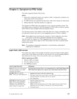
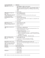
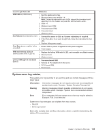
Level 2 Light Path LED FRU/action VRM LED on (VRM failure) 1. See the system-error log. 2. Microprocessor power module 1-4. Note: To see microprocessor error LEDs, remove the processor-board assembly from the chassis, and press the LED Activation switch. 3. VRM 1-4. 4. Midplane-board VRM. 5. Processor-board VRM. 6. Processor board. 7. Midplane board. Non Redund (nonredundancy lost) 1. Connect the server to 220v ac if power redundancy is required. 2. If the PSx LED is lit on Level 2 Light Path, follow the instructions for that LED. 3. Replace failing power supply. Over Spec (power supplies' rating 1. Ensure that ac power is applied to both power supplies. exceeded) 2. Power supply. VRM and memory LEDs on (memory board level 3 LED on) 1. Replace the failing VRM with lit LED, and re-enable any failed memory. 2. Memory board. 3. Midplane board. Level 2 VRM LED on and board LED on 1. Processor-board VRM. 2. Remove all PCI adapters from the server. 3. PCI-X board VRM. 4. PCI-X board. System-error log entries The system-error log is similar to an event log and can contain messages of three major types: Information Information messages do not require action and record significant system-level events. Example: 'System Complex Powered Up' Warning Warning messages indicate possible problems but do not require immediate action. Example: 'System over recommended ambient temperature' Error Error messages indicate system errors that may require attention. Example: 'Fan 2 not detected' System-error log messages can originate from two sources. v SAL/EFI v Service processor Each entry contains date and time information, which is useful in determining the nature of the occurrence. Chapter 6. Symptom-to-FRU index 149
-
 1
1 -
2
-
3
-
4
-
5
-
6
-
7
-
8
-
9
-
10
-
11
-
12
-
13
-
14
-
15
-
16
-
17
-
18
-
19
-
20
-
21
-
22
-
23
-
24
-
25
-
26
-
27
-
28
-
29
-
30
-
31
-
32
-
33
-
34
-
35
-
36
-
37
-
38
-
39
-
40
-
41
-
42
-
43
-
44
-
45
-
46
-
47
-
48
-
49
-
50
-
51
-
52
-
53
-
54
-
55
-
56
-
57
-
58
-
59
-
60
-
61
-
62
-
63
-
64
-
65
-
66
-
67
-
68
-
69
-
70
-
71
-
72
-
73
-
74
-
75
-
76
-
77
-
78
-
79
-
80
-
81
-
82
-
83
-
84
-
85
-
86
-
87
-
88
-
89
-
90
-
91
-
92
-
93
-
94
-
95
-
96
-
97
-
98
-
99
-
100
-
101
-
102
-
103
-
104
-
105
-
106
-
107
-
108
-
109
-
110
-
111
-
112
-
113
-
114
-
115
-
116
-
117
-
118
-
119
-
120
-
121
-
122
-
123
-
124
-
125
-
126
-
127
-
128
-
129
-
130
-
131
-
132
-
133
-
134
-
135
-
136
-
137
-
138
-
139
-
140
-
141
-
142
-
143
-
144
-
145
-
146
-
147
-
148
-
149
-
150
-
151
-
152
-
153
-
 154
154 -
 155
155 -
 156
156 -
 157
157 -
 158
158 -
 159
159 -
 160
160 -
 161
161 -
 162
162 -
 163
163 -
 164
164 -
165
-
166
-
167
-
168
-
169
-
170
-
171
-
172
-
173
-
174
-
175
-
176
-
177
-
178
-
179
-
180
-
181
-
182
-
183
-
184
-
185
-
186
-
187
-
188
-
189
-
190
-
191
-
192
-
193
-
194
-
195
-
196
-
197
-
198
-
199
-
200
-
201
-
202
-
203
-
204
-
205
-
206
-
207
-
208
-
209
-
210
-
211
-
212
-
213
-
214
-
215
-
216
-
217
-
218
-
219
-
220
-
221
-
222
-
223
-
224
-
225
-
226
-
227
-
228
-
229
-
230
-
231
-
232
-
233
-
234
-
235
-
236
-
237
-
238
-
239
-
240
-
241
-
242
-
243
-
244
-
245
-
246
-
247
-
248
-
249
-
250
-
251
-
252
-
253
-
254
-
255
-
256
-
257
-
258
-
259
-
260
-
261
-
262
 |
 |
