IBM 86884RX Maintenance Manual - Page 150
Memory-board, retaining, latches
 |
View all IBM 86884RX manuals
Add to My Manuals
Save this manual to your list of manuals |
Page 150 highlights
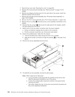
4. Insert your fingers in the two thumb holes, and push toward the outside edges of the card until the card is released. Finger holes Latches 5. Pull the card out of the server. 6. To replace the media bay card, reverse the previous steps. Memory-board retaining latches This section contains instructions for removing the memory-board retaining latches from the processor-board assembly. Before you begin: v Read "Installation guidelines" on page 77. v Read the safety notices at "Safety notices (multilingual translations)" on page 201. v Read "Handling static-sensitive devices" on page 200. Complete the following steps to replace the memory-board retaining latches: 1. Turn off the server (see "Turning off the server" on page 8), and disconnect all power cords and external cables. 2. Open the cover (see "Opening the cover" on page 88). 3. Pull open the memory-board retaining latches, and remove the memory-board assembly. See "Memory board" on page 115 for details. 4. Remove the shipping thumbscrews from the right side of the server, and lift the retention bracket from the server. 5. Remove the processor-board assembly from the server (see "Processor-board assembly" on page 119). 6. Set the processor-board assembly on a static-free, clean work surface. 7. Remove the screws securing the memory-board retaining latches to the processor-board assembly. 8. Remove the memory-board retaining latches and the retention spring from the processor-board assembly; then, remove the the locking slides from the processor-board assembly. 140 IBM xSeries 450 Type 8688: Hardware Maintenance Manual and Troubleshooting Guide
-
 1
1 -
2
-
3
-
4
-
5
-
6
-
7
-
8
-
9
-
10
-
11
-
12
-
13
-
14
-
15
-
16
-
17
-
18
-
19
-
20
-
21
-
22
-
23
-
24
-
25
-
26
-
27
-
28
-
29
-
30
-
31
-
32
-
33
-
34
-
35
-
36
-
37
-
38
-
39
-
40
-
41
-
42
-
43
-
44
-
45
-
46
-
47
-
48
-
49
-
50
-
51
-
52
-
53
-
54
-
55
-
56
-
57
-
58
-
59
-
60
-
61
-
62
-
63
-
64
-
65
-
66
-
67
-
68
-
69
-
70
-
71
-
72
-
73
-
74
-
75
-
76
-
77
-
78
-
79
-
80
-
81
-
82
-
83
-
84
-
85
-
86
-
87
-
88
-
89
-
90
-
91
-
92
-
93
-
94
-
95
-
96
-
97
-
98
-
99
-
100
-
101
-
102
-
103
-
104
-
105
-
106
-
107
-
108
-
109
-
110
-
111
-
112
-
113
-
114
-
115
-
116
-
117
-
118
-
119
-
120
-
121
-
122
-
123
-
124
-
125
-
126
-
127
-
128
-
129
-
130
-
131
-
132
-
133
-
134
-
135
-
136
-
137
-
138
-
139
-
140
-
141
-
142
-
143
-
144
-
 145
145 -
 146
146 -
 147
147 -
 148
148 -
 149
149 -
 150
150 -
 151
151 -
 152
152 -
 153
153 -
 154
154 -
 155
155 -
156
-
157
-
158
-
159
-
160
-
161
-
162
-
163
-
164
-
165
-
166
-
167
-
168
-
169
-
170
-
171
-
172
-
173
-
174
-
175
-
176
-
177
-
178
-
179
-
180
-
181
-
182
-
183
-
184
-
185
-
186
-
187
-
188
-
189
-
190
-
191
-
192
-
193
-
194
-
195
-
196
-
197
-
198
-
199
-
200
-
201
-
202
-
203
-
204
-
205
-
206
-
207
-
208
-
209
-
210
-
211
-
212
-
213
-
214
-
215
-
216
-
217
-
218
-
219
-
220
-
221
-
222
-
223
-
224
-
225
-
226
-
227
-
228
-
229
-
230
-
231
-
232
-
233
-
234
-
235
-
236
-
237
-
238
-
239
-
240
-
241
-
242
-
243
-
244
-
245
-
246
-
247
-
248
-
249
-
250
-
251
-
252
-
253
-
254
-
255
-
256
-
257
-
258
-
259
-
260
-
261
-
262
 |
 |
