IBM 86884RX Maintenance Manual - Page 152
processor-board
 |
View all IBM 86884RX manuals
Add to My Manuals
Save this manual to your list of manuals |
Page 152 highlights
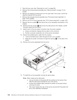
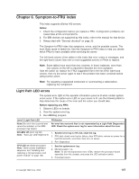
4. Open the top cover (see "Opening the cover" on page 88). 5. Remove the memory-board assembly (see "Memory board" on page 115 for details). 6. Remove the shipping thumbscrews from the right side of the server, and lift the retention bracket from the server. 7. Remove the processor-board assembly (see "Processor-board assembly" on page 119 for details). 8. Remove the PCI-X board assembly (see "PCI-X board assembly" on page 123). 9. Remove the two screws 1 that secure the ac box assembly mechanism to the chassis. 10. Remove the two screws 2 that secure the side panel to the chassis, and lift the panel away from the server. 11. Detach each of the two power connectors near the power supplies: a. Using a screwdriver, depress the two tabs on the connector. b. Pull the connector toward the rear of the server and detach. 12. Detach the bundled power cable from the chassis: a. Pull the bundled power cable through the slot in the crossbar. b. Slide the two power connectors through the opening 3 on the side of the server. 13. Remove the ac box assembly from the server. NOTE: FOR PROPER FRONT OF BOX AIRFLOW, NOTE: FOR PROPER AIRFLOW, FRONT OF BOX REPLACE FAN WITHIN 2 MINUTES REPLACE FAN WITHIN 2 MINUTES 14. To install the ac box assembly, reverse the above steps. Note: When replacing the side panel: a. Line up the tabs on the panel with the notches on the server, then slide the side panel towards the rear of the server. b. Position the bundled cable towards the bottom of the panel before securing the panel. c. The screw nearest the rear of the server secures both the panel and the ac box assembly mechanism. 142 IBM xSeries 450 Type 8688: Hardware Maintenance Manual and Troubleshooting Guide
-
 1
1 -
2
-
3
-
4
-
5
-
6
-
7
-
8
-
9
-
10
-
11
-
12
-
13
-
14
-
15
-
16
-
17
-
18
-
19
-
20
-
21
-
22
-
23
-
24
-
25
-
26
-
27
-
28
-
29
-
30
-
31
-
32
-
33
-
34
-
35
-
36
-
37
-
38
-
39
-
40
-
41
-
42
-
43
-
44
-
45
-
46
-
47
-
48
-
49
-
50
-
51
-
52
-
53
-
54
-
55
-
56
-
57
-
58
-
59
-
60
-
61
-
62
-
63
-
64
-
65
-
66
-
67
-
68
-
69
-
70
-
71
-
72
-
73
-
74
-
75
-
76
-
77
-
78
-
79
-
80
-
81
-
82
-
83
-
84
-
85
-
86
-
87
-
88
-
89
-
90
-
91
-
92
-
93
-
94
-
95
-
96
-
97
-
98
-
99
-
100
-
101
-
102
-
103
-
104
-
105
-
106
-
107
-
108
-
109
-
110
-
111
-
112
-
113
-
114
-
115
-
116
-
117
-
118
-
119
-
120
-
121
-
122
-
123
-
124
-
125
-
126
-
127
-
128
-
129
-
130
-
131
-
132
-
133
-
134
-
135
-
136
-
137
-
138
-
139
-
140
-
141
-
142
-
143
-
144
-
145
-
146
-
 147
147 -
 148
148 -
 149
149 -
 150
150 -
 151
151 -
 152
152 -
 153
153 -
 154
154 -
 155
155 -
 156
156 -
 157
157 -
158
-
159
-
160
-
161
-
162
-
163
-
164
-
165
-
166
-
167
-
168
-
169
-
170
-
171
-
172
-
173
-
174
-
175
-
176
-
177
-
178
-
179
-
180
-
181
-
182
-
183
-
184
-
185
-
186
-
187
-
188
-
189
-
190
-
191
-
192
-
193
-
194
-
195
-
196
-
197
-
198
-
199
-
200
-
201
-
202
-
203
-
204
-
205
-
206
-
207
-
208
-
209
-
210
-
211
-
212
-
213
-
214
-
215
-
216
-
217
-
218
-
219
-
220
-
221
-
222
-
223
-
224
-
225
-
226
-
227
-
228
-
229
-
230
-
231
-
232
-
233
-
234
-
235
-
236
-
237
-
238
-
239
-
240
-
241
-
242
-
243
-
244
-
245
-
246
-
247
-
248
-
249
-
250
-
251
-
252
-
253
-
254
-
255
-
256
-
257
-
258
-
259
-
260
-
261
-
262
 |
 |
