Intel BX80605I7870 Data Sheet - Page 51
Mc_smi_spare_cntrl, Mc_reset_control
 |
UPC - 735858210461
View all Intel BX80605I7870 manuals
Add to My Manuals
Save this manual to your list of manuals |
Page 51 highlights
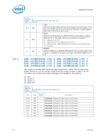
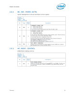
Register Description 2.8.4 2.8.5 MC_SMI_SPARE_CNTRL System Management Interrupt and Spare control register. Device: 3 Function: 0 Offset: 54h Access as a Dword Bit 16 15 14:0 Type RW RW RW Reset Value Description INTERRUPT_SELECT_NMI 0 1 = Enable NMI signaling. 0 = Disable NMI signaling. If both NMI and SMI enable bits are set, then only SMI is sent. INTERRUPT_SELECT_SMI 1 = Enable SMI signaling. 0 = Disable SMI signaling. If both NMI and SMI enable bits are set, then only SMI is sent. This bit functions 0 the same way in Mirror and Independent Modes. The possible SMI events enabled by this bit are: Any one of the error counters MC_COR_ECC_CNT_X meets the value of SMI_ERROR_THRESHOLD field of this register. MC_SSRSTATUS.CMPLT bit is set to 1. MC_RAS_STATUS.REDUNDANCY_LOSS bit is set to 1. SMI_ERROR_THRESHOLD 0 Defines the error threshold to compare against the per-DIMM error counters MC_COR_ECC_CNT_X, which are also 15 bits. MC_RESET_CONTROL DIMM Reset enabling controls. Device: 3 Function: 0 Offset: 5Ch Access as a Dword Bit Type Reset Value Description BIOS_RESET_ENABLE 0 WO 0 When set, MC takes over control of driving RESET to the DIMMs. This bit is set on S3 exit and cold boot to take over RESET driving responsibility from the physical layer. Datasheet 51
-
 1
1 -
2
-
3
-
4
-
5
-
6
-
7
-
8
-
9
-
10
-
11
-
12
-
13
-
14
-
15
-
16
-
17
-
18
-
19
-
20
-
21
-
22
-
23
-
24
-
25
-
26
-
27
-
28
-
29
-
30
-
31
-
32
-
33
-
34
-
35
-
36
-
37
-
38
-
39
-
40
-
41
-
42
-
43
-
44
-
45
-
 46
46 -
 47
47 -
 48
48 -
 49
49 -
 50
50 -
 51
51 -
 52
52 -
 53
53 -
 54
54 -
 55
55 -
 56
56 -
57
-
58
-
59
-
60
-
61
-
62
-
63
-
64
-
65
-
66
-
67
-
68
-
69
-
70
-
71
-
72
-
73
-
74
-
75
-
76
-
77
-
78
-
79
-
80
-
81
-
82
-
83
-
84
-
85
-
86
-
87
-
88
-
89
-
90
-
91
-
92
-
93
-
94
-
95
-
96
-
97
-
98
 |
 |
