Intel BX80605I7870 Data Sheet - Page 83
Error Injection Implementation
 |
UPC - 735858210461
View all Intel BX80605I7870 manuals
Add to My Manuals
Save this manual to your list of manuals |
Page 83 highlights
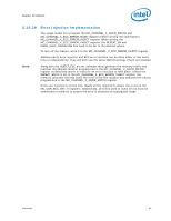
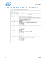
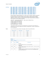
Register Description 2.10.39 Error Injection Implementation The usage model is to program the MC_CHANNEL_X_ADDR_MATCH and MC_CHANNEL_X_ECC_ERROR_MASK registers before writing the command in MC_CHANNEL_X_ECC_ERROR_INJECT register. When writing the MC_CHANNEL_X_ECC_ERROR_INJECT register, the REPEAT_EN and MASK_HALF_CACHELINE bits need to be set to the desired values. To turn off the feature, write 0 to the MC_CHANNEL_X_ECC_ERROR_INJECT register. Address parity error injection and ECC error injection can be done either at the same time or independently. They will both use the same MATCH settings if both are enabled. Note: Along with the INJECT_ECC bit set, software must generate the memory traffic that matches the address location programmed in the MC_CHANNEL_X_ADDR_MATCH register as described above in order for an error injection to take place. Unless the REPEAT_EN bit is set in the MC_CHANNEL_X_ECC_ERROR_INJECT register, the memory controller will only inject the error to the first location that matches the criteria programmed in the MC_CHANNEL_X_ADDR_MATCH register. Errors are injected on writes only. Reads will be required to detect the errors in the MC_COR_ECC_CNT_X registers. Additionally, all writes used to inject errors must be committed to memory to ensure the error is detected on subsequent reads. Datasheet 83
-
 1
1 -
2
-
3
-
4
-
5
-
6
-
7
-
8
-
9
-
10
-
11
-
12
-
13
-
14
-
15
-
16
-
17
-
18
-
19
-
20
-
21
-
22
-
23
-
24
-
25
-
26
-
27
-
28
-
29
-
30
-
31
-
32
-
33
-
34
-
35
-
36
-
37
-
38
-
39
-
40
-
41
-
42
-
43
-
44
-
45
-
46
-
47
-
48
-
49
-
50
-
51
-
52
-
53
-
54
-
55
-
56
-
57
-
58
-
59
-
60
-
61
-
62
-
63
-
64
-
65
-
66
-
67
-
68
-
69
-
70
-
71
-
72
-
73
-
74
-
75
-
76
-
77
-
 78
78 -
 79
79 -
 80
80 -
 81
81 -
 82
82 -
 83
83 -
 84
84 -
 85
85 -
 86
86 -
 87
87 -
 88
88 -
89
-
90
-
91
-
92
-
93
-
94
-
95
-
96
-
97
-
98
 |
 |
