Intel SE7501HG2 Product Guide - Page 20
NIC Connector and Status LEDs, ACPI, CAUTION - processor support
 |
View all Intel SE7501HG2 manuals
Add to My Manuals
Save this manual to your list of manuals |
Page 20 highlights
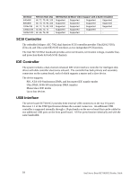
NIC Connector and Status LEDs The 82546EB controller provides two RJ45 ports, each of which provides two LEDs, one to the left of each connector and the other to the right of the each connector when looking at the I/O area from the back of the board. The LEDs to the left of each connector indicate the connection speed and the right connectors indicate transmit / receive activity link/activity on the LAN and the speed of operation. See the following table for an overview. Table 3. 10/100/1000 Megabit LEDs LED Location LED State Off Left of each RJ45 port Green Yellow Right of each RJ45 port On Blinking NIC State 10-Mbps 100-Mbps 1000-Mbps On Transmit / Receive activity ACPI The SE7501HG2 supports the Advanced Configuration and Power Interface (ACPI) as defined by the ACPI 1.0b. An ACPI-aware operating system can put the system into a sleep state in which the hard drives spin down, the system fans stop, and all processing is halted. In this state the power supply is still on and the processors dissipate some power, so the power supply fan and processor fans continue to run. ✏ NOTE ACPI requires an operating system that supports this feature. The server board supports sleep states S0, S1, S4, and S5. When the server board is operating in ACPI mode, the operating system retains control of the system and the OS policy determines the entry methods and wake-up sources for each sleep state - sleep entry and wake-up event capabilities are provided by the hardware but are enabled by the operating system. • S0: Normal running state. • S1: DC Power remains on. The operating system saves the context and enters a low-power state. The system can wake from the S1 state using a PS/2 keyboard, mouse, or USB device, by pressing the power button press, or from a wakeup event. • S4: Hibernate or Save to Disk. The memory and machine state are saved to disk. Pressing the power button or another wakeup event restores the system state from the disk and resumes normal operation. This assumes that no hardware changes were made to the system while it was off. • S5: Soft off. Only the RTC section of the chip set is running in this state. CAUTION The system is off only when the AC power is disconnected. 20 Intel Server Board SE7501HG2 Product Guide
-
 1
1 -
2
-
3
-
4
-
5
-
6
-
7
-
8
-
9
-
10
-
11
-
12
-
13
-
14
-
 15
15 -
 16
16 -
 17
17 -
 18
18 -
 19
19 -
 20
20 -
 21
21 -
 22
22 -
 23
23 -
 24
24 -
 25
25 -
26
-
27
-
28
-
29
-
30
-
31
-
32
-
33
-
34
-
35
-
36
-
37
-
38
-
39
-
40
-
41
-
42
-
43
-
44
-
45
-
46
-
47
-
48
-
49
-
50
-
51
-
52
-
53
-
54
-
55
-
56
-
57
-
58
-
59
-
60
-
61
-
62
-
63
-
64
-
65
-
66
-
67
-
68
-
69
-
70
-
71
-
72
-
73
-
74
-
75
-
76
-
77
-
78
-
79
-
80
-
81
-
82
-
83
-
84
-
85
-
86
-
87
-
88
-
89
-
90
-
91
-
92
-
93
-
94
-
95
-
96
-
97
-
98
-
99
-
100
-
101
-
102
-
103
-
104
-
105
-
106
-
107
-
108
-
109
-
110
-
111
-
112
-
113
-
114
-
115
-
116
-
117
-
118
-
119
-
120
-
121
-
122
-
123
-
124
-
125
-
126
-
127
-
128
-
129
-
130
-
131
-
132
-
133
-
134
-
135
-
136
-
137
-
138
-
139
-
140
 |
 |