Intel SE7501HG2 Product Guide - Page 54
Making Connections to the Server Board,
 |
View all Intel SE7501HG2 manuals
Add to My Manuals
Save this manual to your list of manuals |
Page 54 highlights
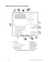
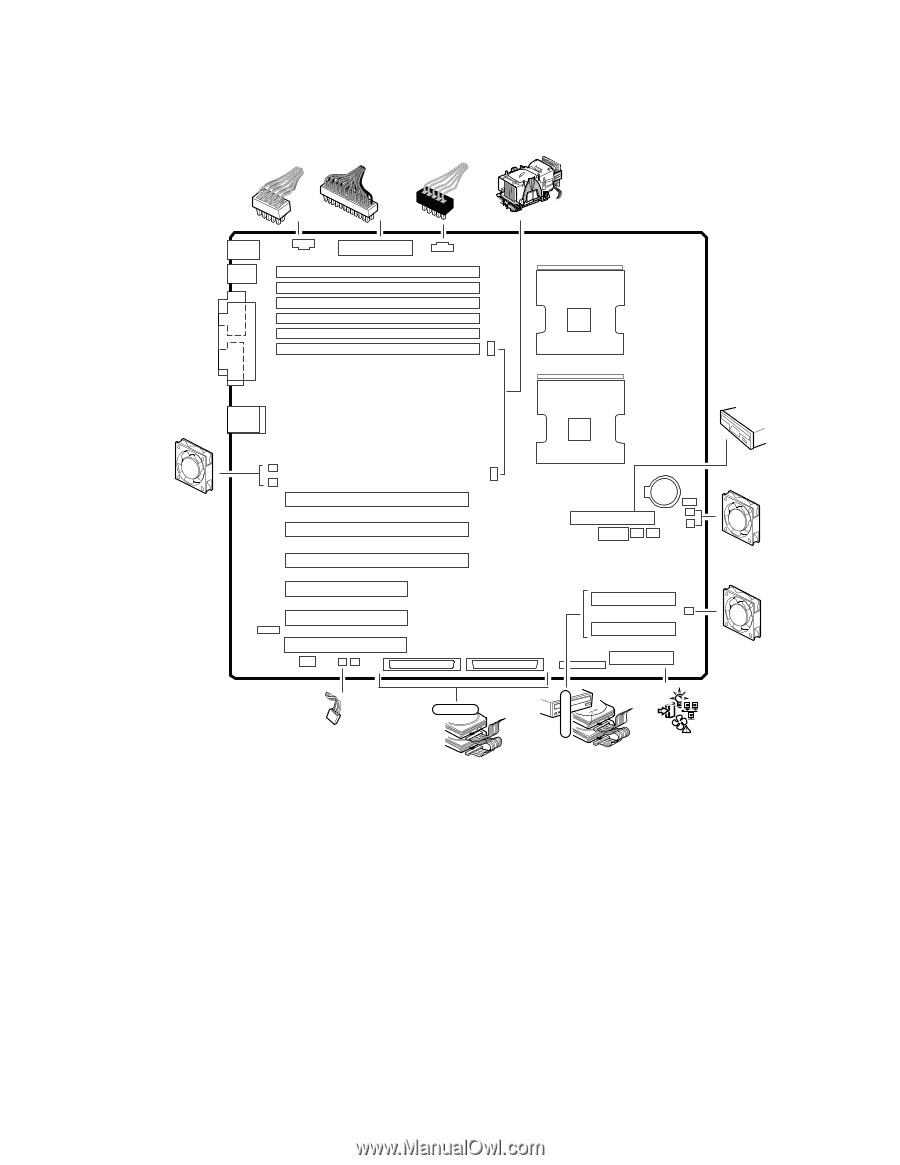
Making Connections to the Server Board A B C 12 V D L E F G K J A I T H SCSI A 1 0 0 A Aux Power B Main Power C +12 V CPU Power D CPU1 Fan (top), CPU2 fan (bottom) E Floppy Disk Drive Connector F System Fan 5 (top), System Fan 4 (bottom) TP00030 G System Fan 3 H Front Panel Connector I Primary IDE (top), Secondary IDE (bottom) J SCSI Channel A (left), SCSI Channel B (right) K Chassis Intrusion L System Fan 1 (top), System Fan 2 (bottom) Figure 28. Making Connections to the Server Board 54 Intel Server Board SE7501HG2 Product Guide
-
 1
1 -
2
-
3
-
4
-
5
-
6
-
7
-
8
-
9
-
10
-
11
-
12
-
13
-
14
-
15
-
16
-
17
-
18
-
19
-
20
-
21
-
22
-
23
-
24
-
25
-
26
-
27
-
28
-
29
-
30
-
31
-
32
-
33
-
34
-
35
-
36
-
37
-
38
-
39
-
40
-
41
-
42
-
43
-
44
-
45
-
46
-
47
-
48
-
 49
49 -
 50
50 -
 51
51 -
 52
52 -
 53
53 -
 54
54 -
 55
55 -
 56
56 -
 57
57 -
 58
58 -
 59
59 -
60
-
61
-
62
-
63
-
64
-
65
-
66
-
67
-
68
-
69
-
70
-
71
-
72
-
73
-
74
-
75
-
76
-
77
-
78
-
79
-
80
-
81
-
82
-
83
-
84
-
85
-
86
-
87
-
88
-
89
-
90
-
91
-
92
-
93
-
94
-
95
-
96
-
97
-
98
-
99
-
100
-
101
-
102
-
103
-
104
-
105
-
106
-
107
-
108
-
109
-
110
-
111
-
112
-
113
-
114
-
115
-
116
-
117
-
118
-
119
-
120
-
121
-
122
-
123
-
124
-
125
-
126
-
127
-
128
-
129
-
130
-
131
-
132
-
133
-
134
-
135
-
136
-
137
-
138
-
139
-
140
 |
 |
Intel Server Board SE7501HG2 Product Guide
54
Making Connections to the Server Board
TP00030
B
C
12 V
A
L
F
G
H
A
T
A
1
0
0
I
E
K
D
SCSI
J
A
Aux Power
G
System Fan 3
B
Main Power
H
Front Panel Connector
C
+12 V CPU Power
I
Primary IDE (top),
Secondary IDE (bottom)
D
CPU1 Fan (top), CPU2 fan (bottom)
J
SCSI Channel A (left),
SCSI Channel B (right)
E
Floppy Disk Drive Connector
K
Chassis Intrusion
F
System Fan 5 (top),
System Fan 4 (bottom)
L
System Fan 1 (top),
System Fan 2 (bottom)
Figure 28.
Making Connections to the Server Board