Intel SE7501HG2 Product Guide - Page 42
the PWT B., Attaching the Wind Tunnel Fan
 |
View all Intel SE7501HG2 manuals
Add to My Manuals
Save this manual to your list of manuals |
Page 42 highlights
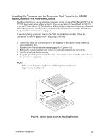
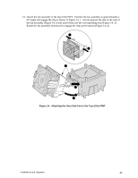
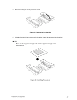
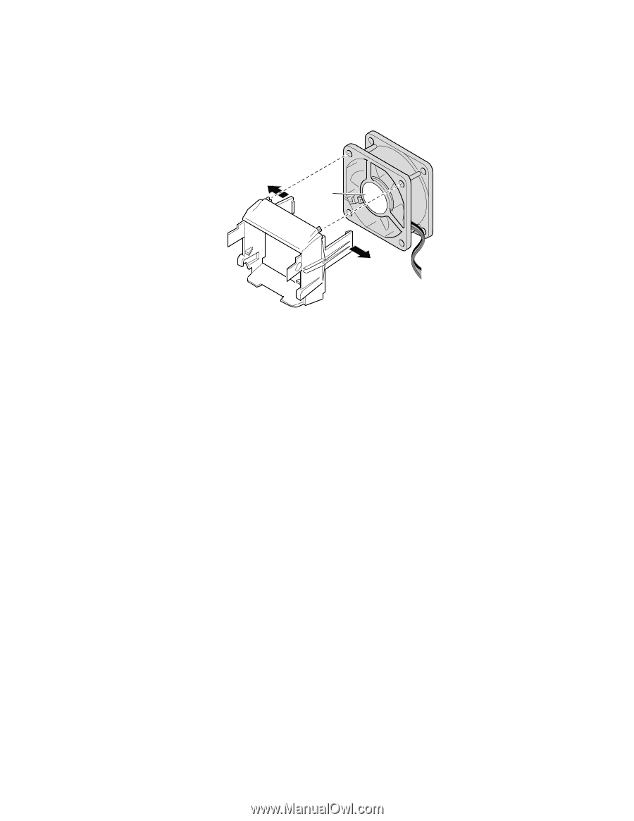
12. Attach the fan between the two large plastic tabs at each side of the fan assembly component of the PWT (Figure 13, B). To ensure that the airflow direction is correct, insert the fan so that the label shows through the assembled unit (Figure 13, A). B A B C OM15041 Figure 13. Attaching the Wind Tunnel Fan 42 Intel Server Board SE7501HG2 Product Guide
-
 1
1 -
2
-
3
-
4
-
5
-
6
-
7
-
8
-
9
-
10
-
11
-
12
-
13
-
14
-
15
-
16
-
17
-
18
-
19
-
20
-
21
-
22
-
23
-
24
-
25
-
26
-
27
-
28
-
29
-
30
-
31
-
32
-
33
-
34
-
35
-
36
-
 37
37 -
 38
38 -
 39
39 -
 40
40 -
 41
41 -
 42
42 -
 43
43 -
 44
44 -
 45
45 -
 46
46 -
 47
47 -
48
-
49
-
50
-
51
-
52
-
53
-
54
-
55
-
56
-
57
-
58
-
59
-
60
-
61
-
62
-
63
-
64
-
65
-
66
-
67
-
68
-
69
-
70
-
71
-
72
-
73
-
74
-
75
-
76
-
77
-
78
-
79
-
80
-
81
-
82
-
83
-
84
-
85
-
86
-
87
-
88
-
89
-
90
-
91
-
92
-
93
-
94
-
95
-
96
-
97
-
98
-
99
-
100
-
101
-
102
-
103
-
104
-
105
-
106
-
107
-
108
-
109
-
110
-
111
-
112
-
113
-
114
-
115
-
116
-
117
-
118
-
119
-
120
-
121
-
122
-
123
-
124
-
125
-
126
-
127
-
128
-
129
-
130
-
131
-
132
-
133
-
134
-
135
-
136
-
137
-
138
-
139
-
140
 |
 |
Intel Server Board SE7501HG2 Product Guide
42
12. Attach the fan between the two large plastic tabs at each side of the fan assembly component of
the PWT (Figure 13, B).
To ensure that the airflow direction is correct, insert the fan so that
the label shows through the assembled unit (Figure 13, A).
OM15041
A
B
B
C
Figure 13.
Attaching the Wind Tunnel Fan