Intel SE7501HG2 Product Guide - Page 56
Finishing Up, WARNING
 |
View all Intel SE7501HG2 manuals
Add to My Manuals
Save this manual to your list of manuals |
Page 56 highlights
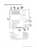
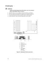
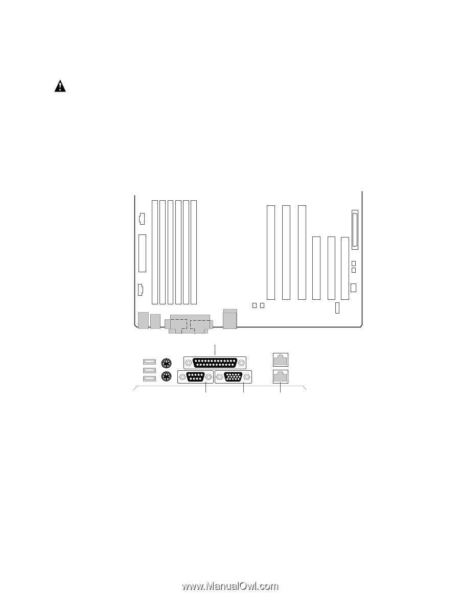
Finishing Up WARNING An electrical shock hazard exists if the chassis cover is not replaced before connecting the chassis AC power. 1. Install the chassis cover according to the instructions for your chassis. 2. See your chassis documentation to complete rack or pedestal installation. 3. Connect the keyboard, mouse and monitor cables to the back panel. 4. Connect the power cable to the back panel and to an AC outlet. C AB D E F A USB 1,2, 3 B Keyboard, Mouse C Parallel Port D Serial A Port E Video F NICs (gigabit) NIC2 top NIC1 bottom Figure 30. Making Back Panel Connections TP00031 56 Intel Server Board SE7501HG2 Product Guide
-
 1
1 -
2
-
3
-
4
-
5
-
6
-
7
-
8
-
9
-
10
-
11
-
12
-
13
-
14
-
15
-
16
-
17
-
18
-
19
-
20
-
21
-
22
-
23
-
24
-
25
-
26
-
27
-
28
-
29
-
30
-
31
-
32
-
33
-
34
-
35
-
36
-
37
-
38
-
39
-
40
-
41
-
42
-
43
-
44
-
45
-
46
-
47
-
48
-
49
-
50
-
 51
51 -
 52
52 -
 53
53 -
 54
54 -
 55
55 -
 56
56 -
 57
57 -
 58
58 -
 59
59 -
 60
60 -
 61
61 -
62
-
63
-
64
-
65
-
66
-
67
-
68
-
69
-
70
-
71
-
72
-
73
-
74
-
75
-
76
-
77
-
78
-
79
-
80
-
81
-
82
-
83
-
84
-
85
-
86
-
87
-
88
-
89
-
90
-
91
-
92
-
93
-
94
-
95
-
96
-
97
-
98
-
99
-
100
-
101
-
102
-
103
-
104
-
105
-
106
-
107
-
108
-
109
-
110
-
111
-
112
-
113
-
114
-
115
-
116
-
117
-
118
-
119
-
120
-
121
-
122
-
123
-
124
-
125
-
126
-
127
-
128
-
129
-
130
-
131
-
132
-
133
-
134
-
135
-
136
-
137
-
138
-
139
-
140
 |
 |
Intel Server Board SE7501HG2 Product Guide
56
Finishing Up
WARNING
An electrical shock hazard exists if the chassis cover is not replaced
before connecting the chassis AC power.
1.
Install the chassis cover according to the instructions for your chassis.
2.
See your chassis documentation to complete rack or pedestal installation.
3.
Connect the keyboard, mouse and monitor cables to the back panel.
4.
Connect the power cable to the back panel and to an AC outlet.
TP00031
A
B
D
E
C
F
A
USB 1,2, 3
B
Keyboard, Mouse
C
Parallel Port
D
Serial A Port
E
Video
F
NICs (gigabit)
NIC2 top
NIC1 bottom
Figure 30.
Making Back Panel Connections