Lexmark 4079 colorjet printer plus Service Manual - Page 101
Power, indicators
 |
View all Lexmark 4079 colorjet printer plus manuals
Add to My Manuals
Save this manual to your list of manuals |
Page 101 highlights
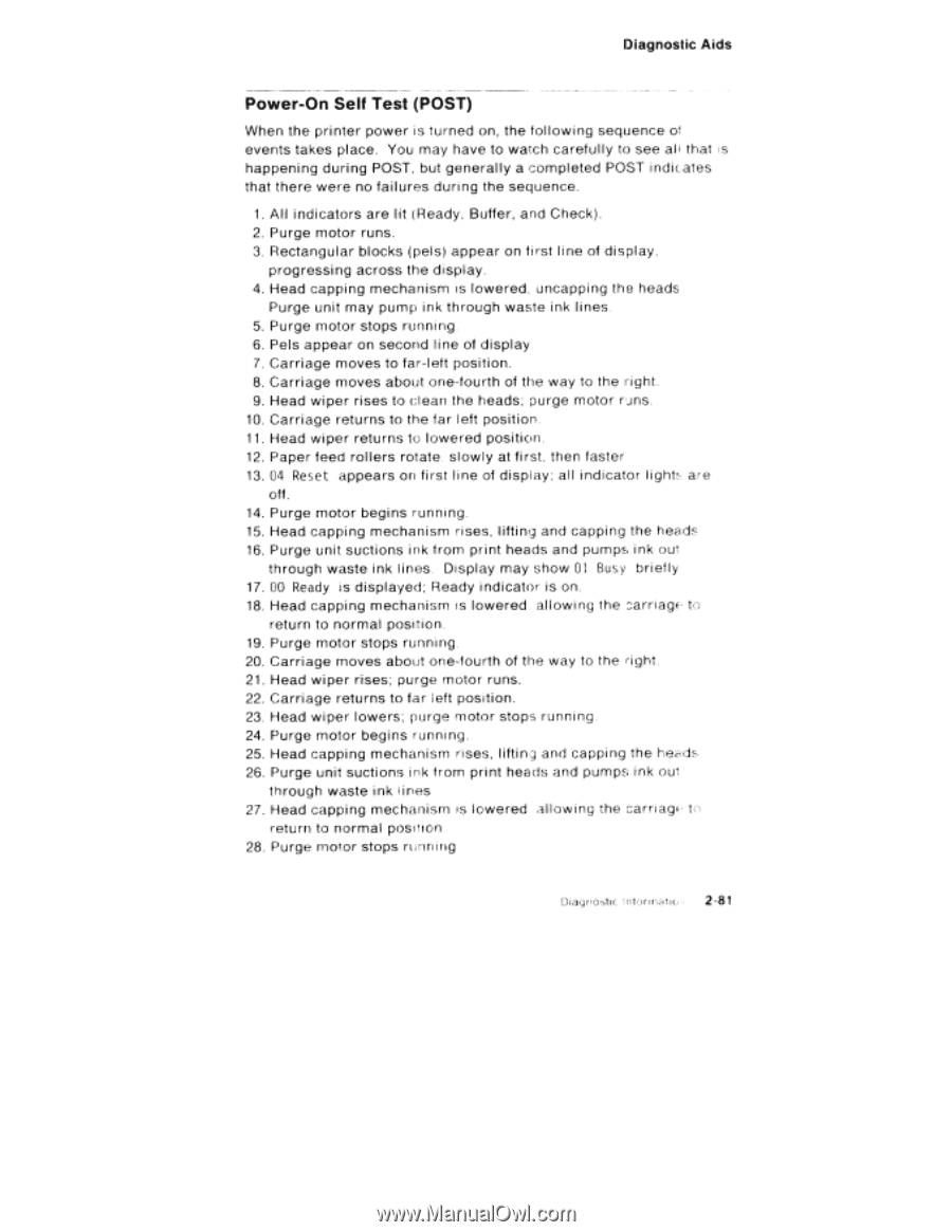
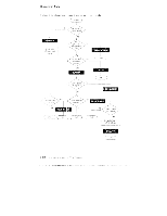
Diagnostic Aids Power-On Self Test (POST) When the printer power is turned on, the following sequence of events takes place. You may have to watch carefully to see al l that is happening during POST, but generally a completed POST indicates that there were no failures during the sequence. 1. All indicators are lit (Ready, Buffer, and Check). 2. Purge motor runs. 3. Rectangular blocks (pels) appear on first l ine of display, progressing across the display. 4. Head capping mechanism is lowered, uncapping the heads Purge unit may pump ink through waste ink lines 5. Purge motor stops running. 6. Pels appear on second line of display. 7. Carriage moves to far-left position. 8. Carriage moves about one-fourth of the way to the right. 9. Head wiper rises to clean the heads; purge motor runs. 10. Carriage returns to the far left position 11. Head wiper returns to lowered position. 12. Paper feed rollers rotate. slowly at first, then faster 13. 04 Reset appears on first line of display; al l indicator light, are oft. 14. Purge motor begins running. 15. Head capping mechanism rises, lifting and capping the heads 16. Purge unit suctions ink from print heads and pumps ink out through waste ink lines. Display may show 01 Busy briefly 17. 00 Ready is displayed; Ready indicator is on. 18. Head capping mechanism is lowered allowing the carriage to return to normal position. 19. Purge motor stops running. 20. Carriage moves about one-fourth of the way to the right. 21. Head wiper rises; purge motor runs. 22. Carriage returns to far left position. 23. Head wiper lowers; purge motor stops running. 24. Purge motor begins running. 25. Head capping mechanism rises, lifting and capping the heads 26. Purge unit suctions irk trom print heads and pumps ink out through waste ink lines 27. Head capping mechanism is lowered allowing the carriagf to return to normal position 28. Purge motor stops running Diagnostic ;ntorrnatic 2-81
-
 1
1 -
2
-
3
-
4
-
5
-
6
-
7
-
8
-
9
-
10
-
11
-
12
-
13
-
14
-
15
-
16
-
17
-
18
-
19
-
20
-
21
-
22
-
23
-
24
-
25
-
26
-
27
-
28
-
29
-
30
-
31
-
32
-
33
-
34
-
35
-
36
-
37
-
38
-
39
-
40
-
41
-
42
-
43
-
44
-
45
-
46
-
47
-
48
-
49
-
50
-
51
-
52
-
53
-
54
-
55
-
56
-
57
-
58
-
59
-
60
-
61
-
62
-
63
-
64
-
65
-
66
-
67
-
68
-
69
-
70
-
71
-
72
-
73
-
74
-
75
-
76
-
77
-
78
-
79
-
80
-
81
-
82
-
83
-
84
-
85
-
86
-
87
-
88
-
89
-
90
-
91
-
92
-
93
-
94
-
95
-
 96
96 -
 97
97 -
 98
98 -
 99
99 -
 100
100 -
 101
101 -
 102
102 -
 103
103 -
 104
104 -
 105
105 -
 106
106 -
107
-
108
-
109
-
110
-
111
-
112
-
113
-
114
-
115
-
116
-
117
-
118
-
119
-
120
-
121
-
122
-
123
-
124
-
125
-
126
-
127
-
128
-
129
-
130
-
131
-
132
-
133
-
134
-
135
-
136
-
137
-
138
-
139
-
140
-
141
-
142
-
143
-
144
-
145
-
146
-
147
-
148
-
149
-
150
-
151
-
152
-
153
-
154
-
155
-
156
-
157
-
158
-
159
-
160
-
161
-
162
-
163
-
164
-
165
-
166
-
167
-
168
-
169
-
170
-
171
-
172
-
173
-
174
-
175
-
176
-
177
-
178
-
179
-
180
-
181
-
182
-
183
-
184
-
185
-
186
-
187
-
188
-
189
-
190
-
191
-
192
-
193
-
194
-
195
-
196
-
197
-
198
-
199
-
200
-
201
-
202
-
203
-
204
-
205
-
206
-
207
-
208
-
209
-
210
-
211
-
212
-
213
-
214
-
215
-
216
-
217
-
218
-
219
-
220
-
221
-
222
-
223
-
224
-
225
-
226
-
227
-
228
-
229
-
230
-
231
-
232
 |
 |