Lexmark 4079 colorjet printer plus Service Manual - Page 43
Logic, Board, Cables, Beeps/Error
 |
View all Lexmark 4079 colorjet printer plus manuals
Add to My Manuals
Save this manual to your list of manuals |
Page 43 highlights
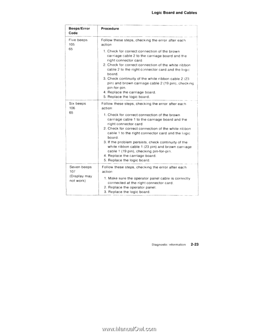
Logic Board and Cables Beeps/Error Code Five beeps 105 65 Six beeps 106 65 Seven beeps 107 (Display may not work) Procedure Follow these steps, checking the error after each action 1. Check for correct connection of the brown carriage cable 2 to the carriage board and the right connector card. 2. Check for correct connection of the white ribbon cable 2 to the right connector card and the logic board. 3. Check continuity of the white ribbon cable 2 (23 pin) and brown carriage cable 2 (19 pin), checking pin-for-pin. 4. Replace the carriage board. 5. Replace the logic board. Follow these steps, checking the error after each action 1. Check for correct connection of the brown carriage cable 1 to the carriage board and the right connector card 2. Check for correct connection of the white ribbon cable 1 to the right connector card and the logic board. 3. If the problem persists, check continuity of the white ribbon cable 1 (23 pin) and brown carr iage cable 1 (19 pin), checking pin-for-pin. 4. Replace the carriage board. 5. Replace the logic board. Follow these steps, checking the error after each action 1. Make sure the operator panel cable is correctly connected at the right connector card. 2. Replace the operator panel. 3. Replace the logic board. Diagnostic information 2-23
-
 1
1 -
2
-
3
-
4
-
5
-
6
-
7
-
8
-
9
-
10
-
11
-
12
-
13
-
14
-
15
-
16
-
17
-
18
-
19
-
20
-
21
-
22
-
23
-
24
-
25
-
26
-
27
-
28
-
29
-
30
-
31
-
32
-
33
-
34
-
35
-
36
-
37
-
 38
38 -
 39
39 -
 40
40 -
 41
41 -
 42
42 -
 43
43 -
 44
44 -
 45
45 -
 46
46 -
 47
47 -
 48
48 -
49
-
50
-
51
-
52
-
53
-
54
-
55
-
56
-
57
-
58
-
59
-
60
-
61
-
62
-
63
-
64
-
65
-
66
-
67
-
68
-
69
-
70
-
71
-
72
-
73
-
74
-
75
-
76
-
77
-
78
-
79
-
80
-
81
-
82
-
83
-
84
-
85
-
86
-
87
-
88
-
89
-
90
-
91
-
92
-
93
-
94
-
95
-
96
-
97
-
98
-
99
-
100
-
101
-
102
-
103
-
104
-
105
-
106
-
107
-
108
-
109
-
110
-
111
-
112
-
113
-
114
-
115
-
116
-
117
-
118
-
119
-
120
-
121
-
122
-
123
-
124
-
125
-
126
-
127
-
128
-
129
-
130
-
131
-
132
-
133
-
134
-
135
-
136
-
137
-
138
-
139
-
140
-
141
-
142
-
143
-
144
-
145
-
146
-
147
-
148
-
149
-
150
-
151
-
152
-
153
-
154
-
155
-
156
-
157
-
158
-
159
-
160
-
161
-
162
-
163
-
164
-
165
-
166
-
167
-
168
-
169
-
170
-
171
-
172
-
173
-
174
-
175
-
176
-
177
-
178
-
179
-
180
-
181
-
182
-
183
-
184
-
185
-
186
-
187
-
188
-
189
-
190
-
191
-
192
-
193
-
194
-
195
-
196
-
197
-
198
-
199
-
200
-
201
-
202
-
203
-
204
-
205
-
206
-
207
-
208
-
209
-
210
-
211
-
212
-
213
-
214
-
215
-
216
-
217
-
218
-
219
-
220
-
221
-
222
-
223
-
224
-
225
-
226
-
227
-
228
-
229
-
230
-
231
-
232
 |
 |