Lexmark 4079 colorjet printer plus Service Manual - Page 141
Adjustment, furniture.
 |
View all Lexmark 4079 colorjet printer plus manuals
Add to My Manuals
Save this manual to your list of manuals |
Page 141 highlights
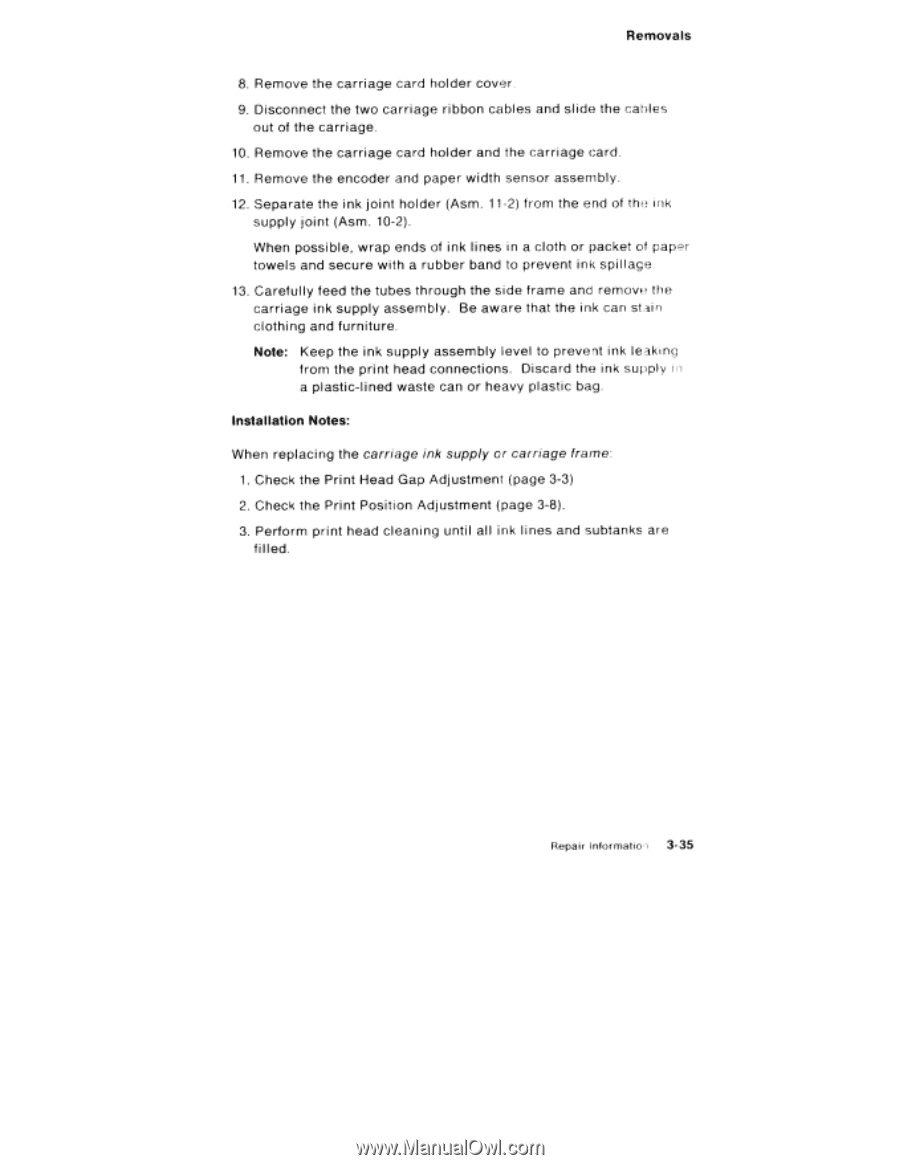
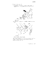
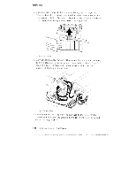
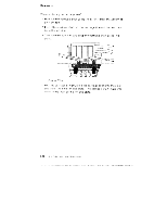
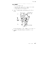
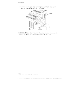
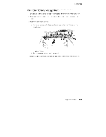
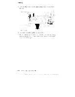
Removals 8. Remove the carriage card holder cover. 9. Disconnect the two carriage ribbon cables and slide the cables out of the carriage. 10. Remove the carriage card holder and the carriage card. 11. Remove the encoder and paper width sensor assembly. 12. Separate the ink joint holder (Asm. 11-2) from the end of the ink supply joint (Asm. 10-2). When possible, wrap ends of ink lines in a cloth or packet of paper towels and secure with a rubber band to prevent ink spillage. 13. Carefully feed the tubes through the side frame anc remove the carriage ink supply assembly. Be aware that the ink can stain clothing and furniture. Note: Keep the ink supply assembly level to prevent ink leaking from the print head connections. Discard the ink supply in a plastic-lined waste can or heavy plastic bag. Installation Notes: When replacing the carriage ink supply or carriage frame: 1. Check the Print Head Gap Adjustment (page 3-3) 2. Check the Print Position Adjustment (page 3-8). 3. Perform print head cleaning until all ink l ines and subtanks are filled. Repair Intormatio 3-35
-
 1
1 -
2
-
3
-
4
-
5
-
6
-
7
-
8
-
9
-
10
-
11
-
12
-
13
-
14
-
15
-
16
-
17
-
18
-
19
-
20
-
21
-
22
-
23
-
24
-
25
-
26
-
27
-
28
-
29
-
30
-
31
-
32
-
33
-
34
-
35
-
36
-
37
-
38
-
39
-
40
-
41
-
42
-
43
-
44
-
45
-
46
-
47
-
48
-
49
-
50
-
51
-
52
-
53
-
54
-
55
-
56
-
57
-
58
-
59
-
60
-
61
-
62
-
63
-
64
-
65
-
66
-
67
-
68
-
69
-
70
-
71
-
72
-
73
-
74
-
75
-
76
-
77
-
78
-
79
-
80
-
81
-
82
-
83
-
84
-
85
-
86
-
87
-
88
-
89
-
90
-
91
-
92
-
93
-
94
-
95
-
96
-
97
-
98
-
99
-
100
-
101
-
102
-
103
-
104
-
105
-
106
-
107
-
108
-
109
-
110
-
111
-
112
-
113
-
114
-
115
-
116
-
117
-
118
-
119
-
120
-
121
-
122
-
123
-
124
-
125
-
126
-
127
-
128
-
129
-
130
-
131
-
132
-
133
-
134
-
135
-
 136
136 -
 137
137 -
 138
138 -
 139
139 -
 140
140 -
 141
141 -
 142
142 -
 143
143 -
 144
144 -
 145
145 -
 146
146 -
147
-
148
-
149
-
150
-
151
-
152
-
153
-
154
-
155
-
156
-
157
-
158
-
159
-
160
-
161
-
162
-
163
-
164
-
165
-
166
-
167
-
168
-
169
-
170
-
171
-
172
-
173
-
174
-
175
-
176
-
177
-
178
-
179
-
180
-
181
-
182
-
183
-
184
-
185
-
186
-
187
-
188
-
189
-
190
-
191
-
192
-
193
-
194
-
195
-
196
-
197
-
198
-
199
-
200
-
201
-
202
-
203
-
204
-
205
-
206
-
207
-
208
-
209
-
210
-
211
-
212
-
213
-
214
-
215
-
216
-
217
-
218
-
219
-
220
-
221
-
222
-
223
-
224
-
225
-
226
-
227
-
228
-
229
-
230
-
231
-
232
 |
 |