Lexmark 4079 colorjet printer plus Service Manual - Page 123
Disconnect, flexing
 |
View all Lexmark 4079 colorjet printer plus manuals
Add to My Manuals
Save this manual to your list of manuals |
Page 123 highlights
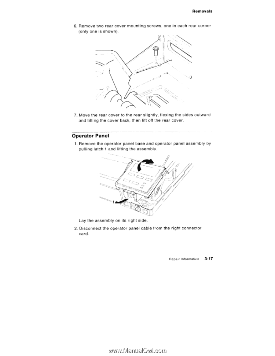
Removals 6. Remove two rear cover mounting screws, one in each rear corner (only one is shown). 7. Move the rear cover to the rear slightly, flexing the sides outward and tilting the cover back, then lift off the rear cover. Operator Panel 1. Remove the operator panel base and operator panel assembly by pulling latch 1 and lifting the assembly. Lay the assembly on its right side. 2. Disconnect the operator panel cable from the right connector card. Repair Infoirnaticn 3-17
-
 1
1 -
2
-
3
-
4
-
5
-
6
-
7
-
8
-
9
-
10
-
11
-
12
-
13
-
14
-
15
-
16
-
17
-
18
-
19
-
20
-
21
-
22
-
23
-
24
-
25
-
26
-
27
-
28
-
29
-
30
-
31
-
32
-
33
-
34
-
35
-
36
-
37
-
38
-
39
-
40
-
41
-
42
-
43
-
44
-
45
-
46
-
47
-
48
-
49
-
50
-
51
-
52
-
53
-
54
-
55
-
56
-
57
-
58
-
59
-
60
-
61
-
62
-
63
-
64
-
65
-
66
-
67
-
68
-
69
-
70
-
71
-
72
-
73
-
74
-
75
-
76
-
77
-
78
-
79
-
80
-
81
-
82
-
83
-
84
-
85
-
86
-
87
-
88
-
89
-
90
-
91
-
92
-
93
-
94
-
95
-
96
-
97
-
98
-
99
-
100
-
101
-
102
-
103
-
104
-
105
-
106
-
107
-
108
-
109
-
110
-
111
-
112
-
113
-
114
-
115
-
116
-
117
-
 118
118 -
 119
119 -
 120
120 -
 121
121 -
 122
122 -
 123
123 -
 124
124 -
 125
125 -
 126
126 -
 127
127 -
 128
128 -
129
-
130
-
131
-
132
-
133
-
134
-
135
-
136
-
137
-
138
-
139
-
140
-
141
-
142
-
143
-
144
-
145
-
146
-
147
-
148
-
149
-
150
-
151
-
152
-
153
-
154
-
155
-
156
-
157
-
158
-
159
-
160
-
161
-
162
-
163
-
164
-
165
-
166
-
167
-
168
-
169
-
170
-
171
-
172
-
173
-
174
-
175
-
176
-
177
-
178
-
179
-
180
-
181
-
182
-
183
-
184
-
185
-
186
-
187
-
188
-
189
-
190
-
191
-
192
-
193
-
194
-
195
-
196
-
197
-
198
-
199
-
200
-
201
-
202
-
203
-
204
-
205
-
206
-
207
-
208
-
209
-
210
-
211
-
212
-
213
-
214
-
215
-
216
-
217
-
218
-
219
-
220
-
221
-
222
-
223
-
224
-
225
-
226
-
227
-
228
-
229
-
230
-
231
-
232
 |
 |
Removals
6.
Remove
two
rear
cover
mounting
screws,
one
in
each
rear
corner
(only
one
is
shown).
7.
Move
the
rear
cover
to
the
rear
sl
ightly,
flexing
the
sides
outward
and
tilting
the
cover
back,
then
lift
off
the
rear
cover.
Operator
Panel
1.
Remove
the
operator
panel
base
and
operator
panel
assembly
by
pulling
latch
1
and
lifting
the
assembly.
Lay
the
assembly
on
its
right
side.
2.
Disconnect
the
operator
panel
cable
from
the
right
connector
card.
Repair
Infoirnaticn
3-17