Lexmark 4079 colorjet printer plus Service Manual - Page 172
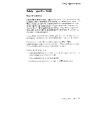
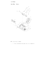
Parts, Point, cations, diagram, llus:rates, single, color, sarrie, pattern., ININNNXIIININIII101
 |
View all Lexmark 4079 colorjet printer plus manuals
Add to My Manuals
Save this manual to your list of manuals |
Page 172 highlights
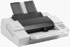
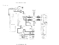
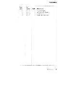
Parts and Test Point Lc,cations The ink, diagram illus:rates the ink flow for a single color ttf ink. Each color of ink has thE, sarrie ink flow pattern. ▪ The irk Cartridge si ,pplies the ink 'C) the sensor i t les Ind also absorbs waste Ink in a separate en arryber. O The Pump (located .n the Purge assemblyi draws ink rani the Ink Cartridge, through tne ink Sensor, through The supply I nes and into the Subtank. ▪ From the Subtank prlk is fed into tie Print Head. ▪ Waste ink troll the , it.tbtank. is drawn to the Pump (torn bined with waste ink front .1he Head Cap mecheini,sm, and Ipwr pE,ii in a. pulsing action -It( tie bottom chamber of the ink :t'arti idge, where it Is itsorbec. 1-8 ir.in/i color JEkiiririei F. 3 4079 HM l3 1. .:* I MN 141101w ININNNXIIININIII111110111111111 1111111, VICIIPP ming poi ow *04 g.,:m61114.1 VAIIIMM /10/1911 : •
-
 1
1 -
2
-
3
-
4
-
5
-
6
-
7
-
8
-
9
-
10
-
11
-
12
-
13
-
14
-
15
-
16
-
17
-
18
-
19
-
20
-
21
-
22
-
23
-
24
-
25
-
26
-
27
-
28
-
29
-
30
-
31
-
32
-
33
-
34
-
35
-
36
-
37
-
38
-
39
-
40
-
41
-
42
-
43
-
44
-
45
-
46
-
47
-
48
-
49
-
50
-
51
-
52
-
53
-
54
-
55
-
56
-
57
-
58
-
59
-
60
-
61
-
62
-
63
-
64
-
65
-
66
-
67
-
68
-
69
-
70
-
71
-
72
-
73
-
74
-
75
-
76
-
77
-
78
-
79
-
80
-
81
-
82
-
83
-
84
-
85
-
86
-
87
-
88
-
89
-
90
-
91
-
92
-
93
-
94
-
95
-
96
-
97
-
98
-
99
-
100
-
101
-
102
-
103
-
104
-
105
-
106
-
107
-
108
-
109
-
110
-
111
-
112
-
113
-
114
-
115
-
116
-
117
-
118
-
119
-
120
-
121
-
122
-
123
-
124
-
125
-
126
-
127
-
128
-
129
-
130
-
131
-
132
-
133
-
134
-
135
-
136
-
137
-
138
-
139
-
140
-
141
-
142
-
143
-
144
-
145
-
146
-
147
-
148
-
149
-
150
-
151
-
152
-
153
-
154
-
155
-
156
-
157
-
158
-
159
-
160
-
161
-
162
-
163
-
164
-
165
-
166
-
 167
167 -
 168
168 -
 169
169 -
 170
170 -
 171
171 -
 172
172 -
 173
173 -
 174
174 -
 175
175 -
 176
176 -
 177
177 -
178
-
179
-
180
-
181
-
182
-
183
-
184
-
185
-
186
-
187
-
188
-
189
-
190
-
191
-
192
-
193
-
194
-
195
-
196
-
197
-
198
-
199
-
200
-
201
-
202
-
203
-
204
-
205
-
206
-
207
-
208
-
209
-
210
-
211
-
212
-
213
-
214
-
215
-
216
-
217
-
218
-
219
-
220
-
221
-
222
-
223
-
224
-
225
-
226
-
227
-
228
-
229
-
230
-
231
-
232
 |
 |