Lexmark 4079 colorjet printer plus Service Manual - Page 129
position, green
 |
View all Lexmark 4079 colorjet printer plus manuals
Add to My Manuals
Save this manual to your list of manuals |
Page 129 highlights
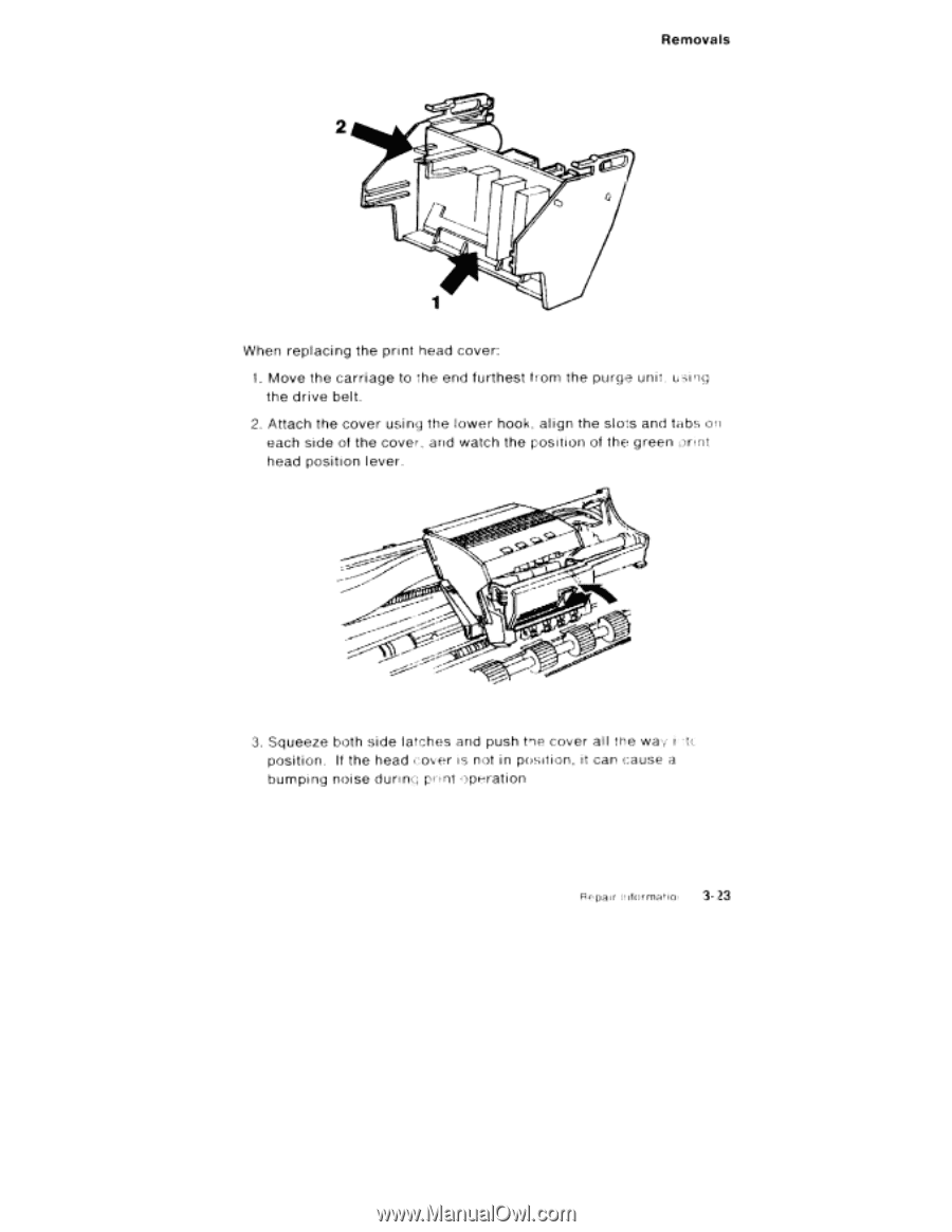
Removals 2 When replacing the print head cover: 1. Move the carriage to the end furthest from the purge unit using the drive belt. 2. Attach the cover using the lower hook, align the slots and tabs on each side of the cover, and watch the position of the green orint head position lever. 3. Squeeze both side latches and push tne cover al l the way i .t(1 position. If the head cover is not in position, it can cause a bumping noise during print operation ' cpar Il iformatioi 3-..t3
-
 1
1 -
2
-
3
-
4
-
5
-
6
-
7
-
8
-
9
-
10
-
11
-
12
-
13
-
14
-
15
-
16
-
17
-
18
-
19
-
20
-
21
-
22
-
23
-
24
-
25
-
26
-
27
-
28
-
29
-
30
-
31
-
32
-
33
-
34
-
35
-
36
-
37
-
38
-
39
-
40
-
41
-
42
-
43
-
44
-
45
-
46
-
47
-
48
-
49
-
50
-
51
-
52
-
53
-
54
-
55
-
56
-
57
-
58
-
59
-
60
-
61
-
62
-
63
-
64
-
65
-
66
-
67
-
68
-
69
-
70
-
71
-
72
-
73
-
74
-
75
-
76
-
77
-
78
-
79
-
80
-
81
-
82
-
83
-
84
-
85
-
86
-
87
-
88
-
89
-
90
-
91
-
92
-
93
-
94
-
95
-
96
-
97
-
98
-
99
-
100
-
101
-
102
-
103
-
104
-
105
-
106
-
107
-
108
-
109
-
110
-
111
-
112
-
113
-
114
-
115
-
116
-
117
-
118
-
119
-
120
-
121
-
122
-
123
-
 124
124 -
 125
125 -
 126
126 -
 127
127 -
 128
128 -
 129
129 -
 130
130 -
 131
131 -
 132
132 -
 133
133 -
 134
134 -
135
-
136
-
137
-
138
-
139
-
140
-
141
-
142
-
143
-
144
-
145
-
146
-
147
-
148
-
149
-
150
-
151
-
152
-
153
-
154
-
155
-
156
-
157
-
158
-
159
-
160
-
161
-
162
-
163
-
164
-
165
-
166
-
167
-
168
-
169
-
170
-
171
-
172
-
173
-
174
-
175
-
176
-
177
-
178
-
179
-
180
-
181
-
182
-
183
-
184
-
185
-
186
-
187
-
188
-
189
-
190
-
191
-
192
-
193
-
194
-
195
-
196
-
197
-
198
-
199
-
200
-
201
-
202
-
203
-
204
-
205
-
206
-
207
-
208
-
209
-
210
-
211
-
212
-
213
-
214
-
215
-
216
-
217
-
218
-
219
-
220
-
221
-
222
-
223
-
224
-
225
-
226
-
227
-
228
-
229
-
230
-
231
-
232
 |
 |
Removals
2
When
replacing
the
print
head
cover:
1.
Move
the
carriage
to
the
end
furthest
from
the
purge
unit
using
the
drive
belt.
2.
Attach
the
cover
using
the
lower
hook,
align
the
slots
and
tabs
on
each
side
of
the
cover,
and
watch
the
position
of
the
green
orint
head
position
lever.
3.
Squeeze
both
side
latches
and
push
tne
cover
al
l
the
way
i
t
.(1
position.
If
the
head
cover
is
not
in
position,
it
can
cause
a
bumping
noise
during
print
operation
'
cpar
Il
iformatioi
3-..t3