Lexmark 4079 colorjet printer plus Service Manual - Page 77
Resistance, Voltage., Voltage, Black, 74-4.46, Magenta, Yellow, Diagnostic, Informatimi
 |
View all Lexmark 4079 colorjet printer plus manuals
Add to My Manuals
Save this manual to your list of manuals |
Page 77 highlights
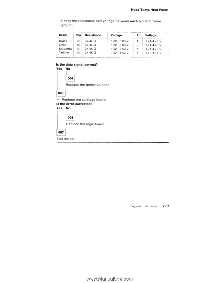
Head Temp/Heat Pulse Check the resistance and voltage between each pin and frame ground. Head Black Cyan Magenta Yellow Pin Resistance 12 3k-4k O 15 3k-4k O 14 3k-4k O 13 3k-4k O Voltage. 1.02 - 5.03 V 1.02 - 5.03 V 1.02 - 5.03 V 1.02 - 5.03 V Pin' Voltage 4 I 74-4 46 V 2 1.74-4.46 V 1 1 74-4.46 V 5 1 74-4.46 V Is the data signal correct? Yes No 004 Replace the defective head. L 005 - Replace the carriage board. Is the error corrected? Yes No [006 Replace the logic board. 007 End the call Diagnostic Informatimi 2-57
-
 1
1 -
2
-
3
-
4
-
5
-
6
-
7
-
8
-
9
-
10
-
11
-
12
-
13
-
14
-
15
-
16
-
17
-
18
-
19
-
20
-
21
-
22
-
23
-
24
-
25
-
26
-
27
-
28
-
29
-
30
-
31
-
32
-
33
-
34
-
35
-
36
-
37
-
38
-
39
-
40
-
41
-
42
-
43
-
44
-
45
-
46
-
47
-
48
-
49
-
50
-
51
-
52
-
53
-
54
-
55
-
56
-
57
-
58
-
59
-
60
-
61
-
62
-
63
-
64
-
65
-
66
-
67
-
68
-
69
-
70
-
71
-
 72
72 -
 73
73 -
 74
74 -
 75
75 -
 76
76 -
 77
77 -
 78
78 -
 79
79 -
 80
80 -
 81
81 -
 82
82 -
83
-
84
-
85
-
86
-
87
-
88
-
89
-
90
-
91
-
92
-
93
-
94
-
95
-
96
-
97
-
98
-
99
-
100
-
101
-
102
-
103
-
104
-
105
-
106
-
107
-
108
-
109
-
110
-
111
-
112
-
113
-
114
-
115
-
116
-
117
-
118
-
119
-
120
-
121
-
122
-
123
-
124
-
125
-
126
-
127
-
128
-
129
-
130
-
131
-
132
-
133
-
134
-
135
-
136
-
137
-
138
-
139
-
140
-
141
-
142
-
143
-
144
-
145
-
146
-
147
-
148
-
149
-
150
-
151
-
152
-
153
-
154
-
155
-
156
-
157
-
158
-
159
-
160
-
161
-
162
-
163
-
164
-
165
-
166
-
167
-
168
-
169
-
170
-
171
-
172
-
173
-
174
-
175
-
176
-
177
-
178
-
179
-
180
-
181
-
182
-
183
-
184
-
185
-
186
-
187
-
188
-
189
-
190
-
191
-
192
-
193
-
194
-
195
-
196
-
197
-
198
-
199
-
200
-
201
-
202
-
203
-
204
-
205
-
206
-
207
-
208
-
209
-
210
-
211
-
212
-
213
-
214
-
215
-
216
-
217
-
218
-
219
-
220
-
221
-
222
-
223
-
224
-
225
-
226
-
227
-
228
-
229
-
230
-
231
-
232
 |
 |
Head
Temp/Heat
Pulse
Check
the
resistance
and
voltage
between
each
pin
and
frame
ground.
Head
Pin
Resistance
Voltage.
Pin'
Voltage
Black
12
3k
-4k
O
1.02
-
5.03
V
4
I
74-4
46
V
Cyan
15
3k
-4k
O
1.02
-
5.03
V
2
1.74-4.46
V
Magenta
14
3k
-4k
O
1.02
-
5.03
V
1
1
74-4.46
V
Yellow
13
3k
-4k
O
1.02
-
5.03
V
5
1
74-4.46
V
Is
the
data
signal
correct?
Yes
No
004
Replace
the
defective
head.
L
005
—
Replace
the
carriage
board.
Is
the
error
corrected?
Yes
No
[006
Replace
the
logic
board.
007
End
the
call
Diagnostic
Informatimi
2-57