Lexmark 4079 colorjet printer plus Service Manual - Page 162
Lower, Frame, Installation, Notes
 |
View all Lexmark 4079 colorjet printer plus manuals
Add to My Manuals
Save this manual to your list of manuals |
Page 162 highlights
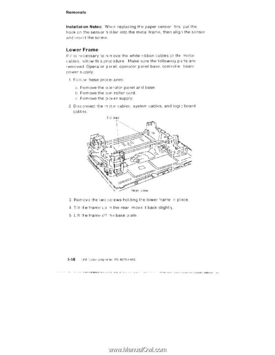
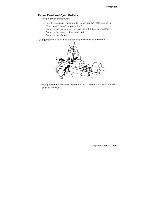
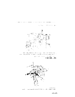
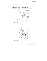
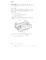
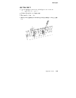
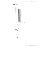
Removals Installation Notes: Whorl replacing the paper sensor, firs: put the hook on the sensor hArler into the metal irarraa, then aligl the sensor and insert the screyy. Lower Frame If it is nrecessary FE IT ove the white ribbon cables or the motor cables, tallow th s prticedure. Make sure the fol lowing pats are removed: Operator panel , operator panel base, control te • boar: , power supply. 1 . Fol low these Remove the operator panel and base. b. Remove the control ler card. c. Re MO V I?, HIE 0; I' supply, 2. Disconnect the ,tri :star cables, system cables, and logi board cables. E c ews "it ;r• \... - N •.• ^5 J V `lcV. -, •5;1N; , \\'• '• ; • ;ie r vieuv 3 Remove the two screws holding the lower 'Frame n place. 4 Ti lt the frame n the rear mova it back slight . 5, Lift the frame p"f • hit base plate. 3-56 1'3 F:Clor Jetprir tel PS 4079 S NI I MI II* loll • 141•111-Mi awe. •I• lb .1,41,114,11111101.04
-
 1
1 -
2
-
3
-
4
-
5
-
6
-
7
-
8
-
9
-
10
-
11
-
12
-
13
-
14
-
15
-
16
-
17
-
18
-
19
-
20
-
21
-
22
-
23
-
24
-
25
-
26
-
27
-
28
-
29
-
30
-
31
-
32
-
33
-
34
-
35
-
36
-
37
-
38
-
39
-
40
-
41
-
42
-
43
-
44
-
45
-
46
-
47
-
48
-
49
-
50
-
51
-
52
-
53
-
54
-
55
-
56
-
57
-
58
-
59
-
60
-
61
-
62
-
63
-
64
-
65
-
66
-
67
-
68
-
69
-
70
-
71
-
72
-
73
-
74
-
75
-
76
-
77
-
78
-
79
-
80
-
81
-
82
-
83
-
84
-
85
-
86
-
87
-
88
-
89
-
90
-
91
-
92
-
93
-
94
-
95
-
96
-
97
-
98
-
99
-
100
-
101
-
102
-
103
-
104
-
105
-
106
-
107
-
108
-
109
-
110
-
111
-
112
-
113
-
114
-
115
-
116
-
117
-
118
-
119
-
120
-
121
-
122
-
123
-
124
-
125
-
126
-
127
-
128
-
129
-
130
-
131
-
132
-
133
-
134
-
135
-
136
-
137
-
138
-
139
-
140
-
141
-
142
-
143
-
144
-
145
-
146
-
147
-
148
-
149
-
150
-
151
-
152
-
153
-
154
-
155
-
156
-
 157
157 -
 158
158 -
 159
159 -
 160
160 -
 161
161 -
 162
162 -
 163
163 -
 164
164 -
 165
165 -
 166
166 -
 167
167 -
168
-
169
-
170
-
171
-
172
-
173
-
174
-
175
-
176
-
177
-
178
-
179
-
180
-
181
-
182
-
183
-
184
-
185
-
186
-
187
-
188
-
189
-
190
-
191
-
192
-
193
-
194
-
195
-
196
-
197
-
198
-
199
-
200
-
201
-
202
-
203
-
204
-
205
-
206
-
207
-
208
-
209
-
210
-
211
-
212
-
213
-
214
-
215
-
216
-
217
-
218
-
219
-
220
-
221
-
222
-
223
-
224
-
225
-
226
-
227
-
228
-
229
-
230
-
231
-
232
 |
 |