Panasonic AW-UE100 Operating Instructions - Page 19
G SDI OUT connector <3G SDI OUT>, Screw: 1/4-20 UNC, ISO 1222 [6.35 mm 1/4 inches]
 |
View all Panasonic AW-UE100 manuals
Add to My Manuals
Save this manual to your list of manuals |
Page 19 highlights
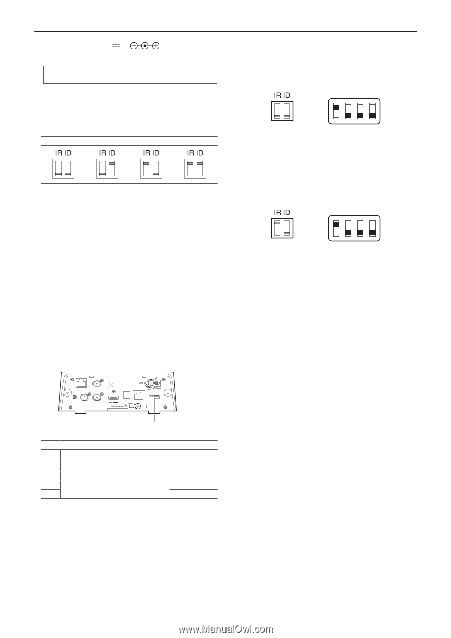
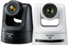
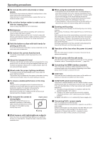
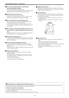
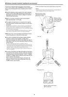
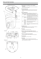
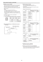
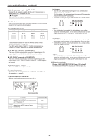
Parts and their functions (continued) 14.DC IN connector Connect the AC adaptor supplied with the unit to this connector to supply the DC 12 V voltage to the unit. „„AC adaptor Be sure to use the supplied AC adaptor. 15.Cable clamp This is used to hold the cable connection to the DC IN connector and prevent it from becoming disconnected. 16.IR ID switches CAM1 CAM2 CAM3 CAM4 These are used to select the ID of the wireless remote control (optional accessory). (→ page 30) The IR ID switch settings "CAM1" to "CAM4" correspond to the to buttons on the wireless remote control. 17.3G SDI OUT connector This is an SDI video signal output connector. Depending upon the output signal format, 3G-SDI or 1.5G-SDI signals are output. 18.12G SDI OUT connector This is an SDI video signal output connector. Depending upon the output signal format, 12G-SDI, 6G-SDI, 3G-SDI or 1.5G-SDI signals are output. 19.HDMI connector This is the HDMI video output connector. 20.Ground connector Connects to the ground connector on a wall outlet, ground bar, etc. for grounding. (→ page 8) 21.Service switches Perform switch settings before turning the unit on. RS-422 G/L IN AUDIO IN 3G SDI OUT 12G SDI OUT IR ID DC IN 12 V LAN LINK ACT SERVICE Initialization 1 • Reset the user authentication settings and host authentication settings for network connection. (This will delete all the registered user information (IDs/passwords) and host information (IP addresses).) • With the IR ID switches and service switches set as shown below, turn on the power of the unit. SW1 SW2 SW3 SW4 ON OFF • When initialization is complete, the status display lamp on the front of the unit blinks green. Set the service switches back to their original positions (SW1 to SW4 all OFF), then restart the unit. Initialization 2 • The unit is reset to the state it was in at the time of purchase. (All camera menu setting values and network setting values are reset.) • With the IR ID switches and service switches set as shown below, turn on the power of the unit. SW1 SW2 SW3 SW4 ON OFF • When initialization is complete, the status display lamp on the front of the unit blinks green. Set the service switches back to their original positions (SW1 to SW4 all OFF), then restart the unit. 22.Tripod screw holes (Screw: 1/4-20 UNC, ISO 1222 [6.35 mm (1/4 inches)]) Use these screw holes when securing the unit to a tripod, etc. Service switches SW1 SW2 SW3 SW4 Function Switches for initialization (Refer to the explanations in "Initialization 1" and "Initialization 2") Always leave at OFF (used for factory adjustments) Factory settings OFF OFF OFF OFF 19
-
 1
1 -
2
-
3
-
4
-
5
-
6
-
7
-
8
-
9
-
10
-
11
-
12
-
13
-
 14
14 -
 15
15 -
 16
16 -
 17
17 -
 18
18 -
 19
19 -
 20
20 -
 21
21 -
 22
22 -
 23
23 -
 24
24 -
25
-
26
-
27
-
28
-
29
-
30
-
31
-
32
-
33
-
34
-
35
-
36
-
37
-
38
-
39
-
40
-
41
-
42
-
43
-
44
-
45
-
46
-
47
-
48
-
49
-
50
-
51
-
52
-
53
-
54
-
55
-
56
-
57
-
58
-
59
-
60
-
61
-
62
-
63
-
64
-
65
-
66
-
67
-
68
-
69
-
70
-
71
-
72
-
73
-
74
-
75
-
76
-
77
-
78
-
79
-
80
-
81
-
82
-
83
-
84
-
85
-
86
-
87
-
88
-
89
-
90
-
91
-
92
-
93
-
94
-
95
-
96
-
97
-
98
-
99
-
100
-
101
-
102
-
103
-
104
-
105
-
106
-
107
-
108
-
109
-
110
-
111
-
112
-
113
-
114
-
115
-
116
-
117
-
118
-
119
-
120
-
121
-
122
-
123
-
124
-
125
-
126
-
127
-
128
-
129
-
130
-
131
-
132
-
133
-
134
-
135
-
136
-
137
-
138
-
139
-
140
-
141
-
142
-
143
-
144
-
145
-
146
-
147
-
148
-
149
-
150
-
151
-
152
-
153
-
154
-
155
-
156
-
157
-
158
-
159
-
160
-
161
-
162
-
163
-
164
-
165
-
166
-
167
-
168
-
169
-
170
-
171
-
172
-
173
-
174
-
175
-
176
-
177
-
178
-
179
-
180
 |
 |