Panasonic AW-UE100 Operating Instructions - Page 70
Output 5/5 screen, UHD Crop 1/2 screen, OSD Off With R‑Tally [Off, On]
 |
View all Panasonic AW-UE100 manuals
Add to My Manuals
Save this manual to your list of manuals |
Page 70 highlights
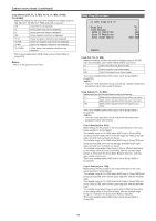
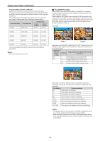
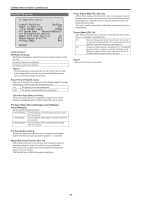
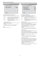
Camera menu items (continued) Output 5/5 screen Output 5/5 OSD Off With R-Tally OSD Status Tally Tally Brightness Status Lamp External Output Output1 Output2 Return Off Off Enable Low Enable Off Off OSD Off With R‑Tally [Off, On] Off or on the function that turns off camera menu, status, crop frame and other displays when red tally signals are received via commands or contacts. When the red tally signal releases, the camera menu display will return. OSD Status [Off, On] Turn the status display during AWB and ABB off/on, or error display when an error occurs. Tally [Enable, Disable] [Disable] or [Enable] is set here for the function which turns on or turns off the tally lamp using the tally control signal. Tally Brightness [Low, Mid, High] Adjust the brightness of the tally LED. Status Lamp [Enable, Disable] [Disable] or [Enable] is set here for the status display lamp. When you want the status display lamp to stay off while this unit is in operation, set to [Disable]. • Even when set to [Disable], the status display lamp may light up when this unit is starting up, updating firmware, or trouble is occurring. External Output Select the signal type output from the External Output signal lines (Output1, Output2) of the RS‑422 connector. (→ page 18) Output1 [Off, R-Tally, G-Tally] Output2 [Off, R-Tally, G-Tally] Off Signal is not output. R-Tally The reception status of the red tally signal is output. G-Tally The reception status of the green tally signal is output. Return Return to the previous menu level. UHD Crop 1/2 screen UHD Crop 1/2 3G SDI Out NDI Out IP Out1 IP Out2 Crop Marker Crop Crop Crop Crop YL+G+MG Return 3G SDI Out [Full, Crop] Make the settings for Full/Crop for images output to the 3G SDI OUT connector. Full FHD down-converted images are output as is without cropping UHD images. Crop Images with FHD cropped from UHD images are output. The images output in this case are those with the crop frame specified in [Crop Out]. This is only enabled when [UHD Crop] is set to [Crop(1080)] or [Crop(720)]. NDI Out [Full, Crop] Makes the settings for Full/Crop for images output to NDI transmission (LAN connector). Full FHD down-converted images are output as is without cropping UHD images. Crop Images with FHD cropped from UHD images are output. The images output in this case are those with the crop frame specified in [Crop Out]. This is only enabled when [UHD Crop] is set to [Crop(1080)] or [Crop(720)]. IP Out1 [Full, Crop] IP Out2 [Full, Crop] Makes the settings for Full/Crop for images output to H.264/H.265/MJPEG transmission (LAN connector). Setting specified in [IP Out1] is applied to images transmitted by each transmission CH1(H.264(1), H.265(1), JPEG(1)). Setting specified in [IP Out2] is applied to images transmitted by each transmission CH2 to CH4(H.264(2) to (4), H.265(2) to (4), JPEG(2) to (3)). Full FHD down-converted images are output as is without cropping UHD images. Crop Images with FHD cropped from UHD images are output. The images output in this case are those with the crop frame specified in [Crop Out]. This is only enabled when [UHD Crop] is set to [Crop(1080)] or [Crop(720)]. When the [Streaming mode] on the web screen is [NDI|HX], [IP Out1] and [IP Out2] will have a linked operation. 70
-
 1
1 -
2
-
3
-
4
-
5
-
6
-
7
-
8
-
9
-
10
-
11
-
12
-
13
-
14
-
15
-
16
-
17
-
18
-
19
-
20
-
21
-
22
-
23
-
24
-
25
-
26
-
27
-
28
-
29
-
30
-
31
-
32
-
33
-
34
-
35
-
36
-
37
-
38
-
39
-
40
-
41
-
42
-
43
-
44
-
45
-
46
-
47
-
48
-
49
-
50
-
51
-
52
-
53
-
54
-
55
-
56
-
57
-
58
-
59
-
60
-
61
-
62
-
63
-
64
-
 65
65 -
 66
66 -
 67
67 -
 68
68 -
 69
69 -
 70
70 -
 71
71 -
 72
72 -
 73
73 -
 74
74 -
 75
75 -
76
-
77
-
78
-
79
-
80
-
81
-
82
-
83
-
84
-
85
-
86
-
87
-
88
-
89
-
90
-
91
-
92
-
93
-
94
-
95
-
96
-
97
-
98
-
99
-
100
-
101
-
102
-
103
-
104
-
105
-
106
-
107
-
108
-
109
-
110
-
111
-
112
-
113
-
114
-
115
-
116
-
117
-
118
-
119
-
120
-
121
-
122
-
123
-
124
-
125
-
126
-
127
-
128
-
129
-
130
-
131
-
132
-
133
-
134
-
135
-
136
-
137
-
138
-
139
-
140
-
141
-
142
-
143
-
144
-
145
-
146
-
147
-
148
-
149
-
150
-
151
-
152
-
153
-
154
-
155
-
156
-
157
-
158
-
159
-
160
-
161
-
162
-
163
-
164
-
165
-
166
-
167
-
168
-
169
-
170
-
171
-
172
-
173
-
174
-
175
-
176
-
177
-
178
-
179
-
180
 |
 |
