Sony PDWHD1500 User Manual (PDW-HD1500 / PDW-F1600 Operation Manual for Firmwa - Page 133
FAM FAM PC REMOTE, Menu items in the 100s, relating to the control panels
 |
View all Sony PDWHD1500 manuals
Add to My Manuals
Save this manual to your list of manuals |
Page 133 highlights
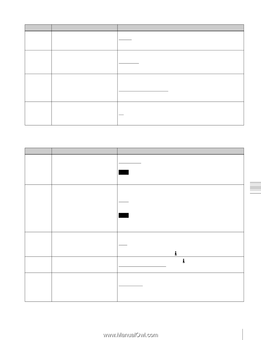
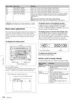
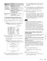
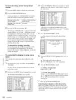
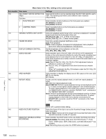
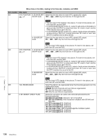
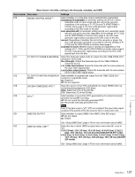
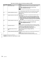
Menu items in the 100s, relating to the control panels Item number Item name Settings 150 REC MODE Select the recording mode. normal: Normal recording mode D.EXC (disc exchange cache): Disc Exchange Cache mode C.REC (clip continuous rec): Clip Continuous Rec mode 151 GUI OPERATION Select whether to disable the display of the Thumbnail Menu and Disc Menu when this unit is in any mode other than stop mode. ena(enable): Do not disable. stop(via stop): Enable the display of menus in the stop mode. dis(disable): Disable. 153 FIND MODE Specify the frame to be cued up when the PREV or NEXT button is pressed. clip: The first frame of the clip R.ST (clip & rec start mark): The frame where a Rec Start essence mark is set (if no essence mark is set, the first frame of the clip) SHOTMARK1: Shot Mark1 154 SINGLE CLIP PLAY MODE Put the unit into single clip playback mode, or exit from single clip playback mode. off: Exits from single clip playback mode. (Puts the unit into continuous playback mode.) on: Puts the unit into single clip playback mode. a) The disc is ejected after recording stops. b) The unit enters stop mode when the PLAY button is pressed. It enters freeze picture mode (jog, shuttle, or variable mode) when the SHTL/JOG button or VAR/JOG button is pressed. Menu items in the 200s, relating to the remote control interface Item number Item name 201 PARA RUN 212 VIDEO REMOTE CONTROL SELECT a) 214 REMOTE INTERFACE 215 i.LINK MODE b) 257 NETWORK ENABLE Settings Select whether to use synchronized operation for two or more VTRs. dis (disable): No synchronized operationena ena (enable): Use synchronized operation Note To use synchronized operation for two or more VTRs, set item 201 to ena on all of the VTRs. Select whether to control the up converter or down converter when controlling the image enhancer from the HKDV-900 or another unit connected to the VIDEO CONTROL connector. down: Control the down-converter. up: Control the up-converter. u&d: Control both the up- and down-converter. Note It is also possible to adjust setup menu item 718 SETUP LEVEL/BLACK LEVEL from the HKDV-900. Hold down the D2 button on the HKDV-900 and rotate the SETUP dial. When the remote control switch is set to REMOTE, select the device from which to remote-control this unit. 9PIN: Device connected to the REMOTE(9P) connector. SDI: Device connected to the SD/HDSDI INPUT connector. i.LINK: Device connected to the (i.LINK) S400 connector. b) Select the connection method for the (i.LINK) S400 connector. FAM (FAM (PC REMOTE)): FAM connection TS: TS connection Select the remote control switch positions which enable network connections. net (network): Only when the switch is set to "NET". n&9P (network & remote(9PIN)): When the switch is set to "NET", and when the switch is set to "REMOTE" and setup menu item 214 is set to "9PIN". c) Chapter 7 Menus Setup Menu 133
-
 1
1 -
2
-
3
-
4
-
5
-
6
-
7
-
8
-
9
-
10
-
11
-
12
-
13
-
14
-
15
-
16
-
17
-
18
-
19
-
20
-
21
-
22
-
23
-
24
-
25
-
26
-
27
-
28
-
29
-
30
-
31
-
32
-
33
-
34
-
35
-
36
-
37
-
38
-
39
-
40
-
41
-
42
-
43
-
44
-
45
-
46
-
47
-
48
-
49
-
50
-
51
-
52
-
53
-
54
-
55
-
56
-
57
-
58
-
59
-
60
-
61
-
62
-
63
-
64
-
65
-
66
-
67
-
68
-
69
-
70
-
71
-
72
-
73
-
74
-
75
-
76
-
77
-
78
-
79
-
80
-
81
-
82
-
83
-
84
-
85
-
86
-
87
-
88
-
89
-
90
-
91
-
92
-
93
-
94
-
95
-
96
-
97
-
98
-
99
-
100
-
101
-
102
-
103
-
104
-
105
-
106
-
107
-
108
-
109
-
110
-
111
-
112
-
113
-
114
-
115
-
116
-
117
-
118
-
119
-
120
-
121
-
122
-
123
-
124
-
125
-
126
-
127
-
 128
128 -
 129
129 -
 130
130 -
 131
131 -
 132
132 -
 133
133 -
 134
134 -
 135
135 -
 136
136 -
 137
137 -
 138
138 -
139
-
140
-
141
-
142
-
143
-
144
-
145
-
146
-
147
-
148
-
149
-
150
-
151
-
152
-
153
-
154
-
155
-
156
-
157
-
158
-
159
-
160
-
161
-
162
-
163
-
164
-
165
-
166
-
167
-
168
-
169
-
170
-
171
-
172
-
173
-
174
-
175
-
176
-
177
-
178
-
179
-
180
-
181
-
182
-
183
-
184
-
185
-
186
-
187
-
188
-
189
-
190
-
191
-
192
-
193
-
194
-
195
-
196
-
197
-
198
 |
 |