Sony PDWHD1500 User Manual (PDW-HD1500 / PDW-F1600 Operation Manual for Firmwa - Page 42
Synchronization Reference Signals
 |
View all Sony PDWHD1500 manuals
Add to My Manuals
Save this manual to your list of manuals |
Page 42 highlights
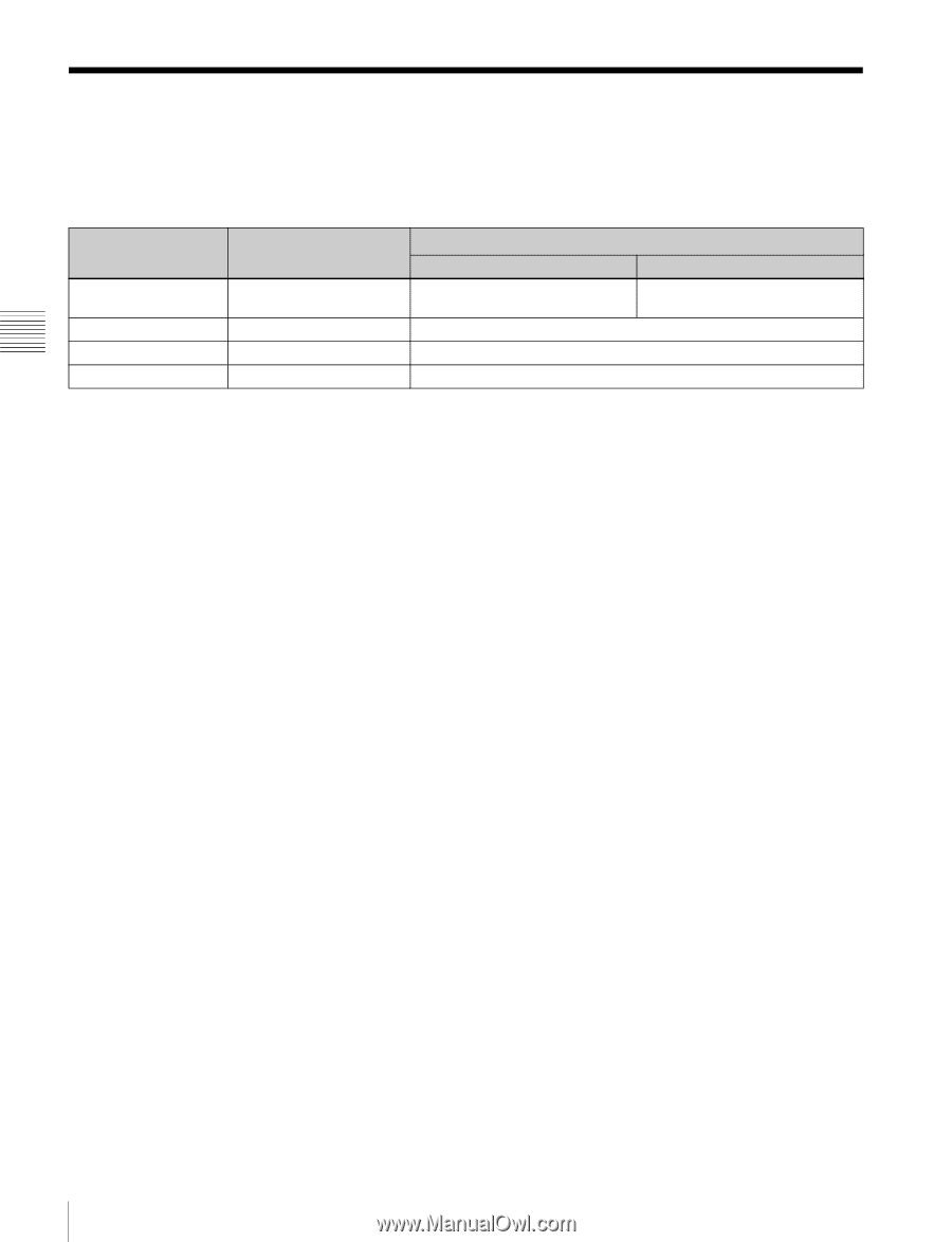
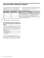
Chapter 3 Preparations Synchronization Reference Signals The synchronization reference signal generator of this unit synchronizes to a reference signal input to the REF. VIDEO INPUT connector or to a video input signal. External synchronization is as follows, depending on the setting of OUT REF on page P6 REF of the function menu, and on the type of the selected input signal. Video output signals are always synchronized to the internal synchronization signal. Input to SD/HDSDI INPUT connector a) Yes Input to REF. VIDEO INPUT connector Yes Setting of OUT REF on page P6 REF b) REF INPUT Synchronize to the signal input to Synchronize to the signal input to the REF. VIDEO INPUT connector the SD/HDSDI INPUT connector Yes No No Yes Synchronize to the signal input to the SD/HDSDI INPUT connector Synchronize to the signal input to the REF. VIDEO INPUT connector No No No external synchronization is made a) Same as when V INPUT on page P1 VIDEO of the function menu is set to "SG". b) FAM and FTP connections always synchronize to the internal synchronization reference signal, regardless of the setting of OUT REF. Synchronization reference signals when you are recording, playing, or editing 720P signals When you are recording, playing, or editing 720P signals, set OUT REF on page P6 REF of the function menu item to "REF", and synchronize the internal reference signal generator of this unit to a reference signal input to the REF. VIDEO INPUT connector. The following reference signals may be used. 720/59.94P system: 1080/59.94i tri-level sync signal, 525 black burst signal 720/50P system: 1080/50i tri-level sync signal, 625 black burst signal When you connect this unit directly to the video I/O connectors of the PDW-F1600/HD1500/F800/700, you can record and dub 720P signals even if you set OUT REF on page P6 REF of the function menu item to "INPUT". 42 Synchronization Reference Signals
-
 1
1 -
2
-
3
-
4
-
5
-
6
-
7
-
8
-
9
-
10
-
11
-
12
-
13
-
14
-
15
-
16
-
17
-
18
-
19
-
20
-
21
-
22
-
23
-
24
-
25
-
26
-
27
-
28
-
29
-
30
-
31
-
32
-
33
-
34
-
35
-
36
-
 37
37 -
 38
38 -
 39
39 -
 40
40 -
 41
41 -
 42
42 -
 43
43 -
 44
44 -
 45
45 -
 46
46 -
 47
47 -
48
-
49
-
50
-
51
-
52
-
53
-
54
-
55
-
56
-
57
-
58
-
59
-
60
-
61
-
62
-
63
-
64
-
65
-
66
-
67
-
68
-
69
-
70
-
71
-
72
-
73
-
74
-
75
-
76
-
77
-
78
-
79
-
80
-
81
-
82
-
83
-
84
-
85
-
86
-
87
-
88
-
89
-
90
-
91
-
92
-
93
-
94
-
95
-
96
-
97
-
98
-
99
-
100
-
101
-
102
-
103
-
104
-
105
-
106
-
107
-
108
-
109
-
110
-
111
-
112
-
113
-
114
-
115
-
116
-
117
-
118
-
119
-
120
-
121
-
122
-
123
-
124
-
125
-
126
-
127
-
128
-
129
-
130
-
131
-
132
-
133
-
134
-
135
-
136
-
137
-
138
-
139
-
140
-
141
-
142
-
143
-
144
-
145
-
146
-
147
-
148
-
149
-
150
-
151
-
152
-
153
-
154
-
155
-
156
-
157
-
158
-
159
-
160
-
161
-
162
-
163
-
164
-
165
-
166
-
167
-
168
-
169
-
170
-
171
-
172
-
173
-
174
-
175
-
176
-
177
-
178
-
179
-
180
-
181
-
182
-
183
-
184
-
185
-
186
-
187
-
188
-
189
-
190
-
191
-
192
-
193
-
194
-
195
-
196
-
197
-
198
 |
 |