Sony PDWHD1500 User Manual (PDW-HD1500 / PDW-F1600 Operation Manual for Firmwa - Page 26
Video monitor display, Reference signal
 |
View all Sony PDWHD1500 manuals
Add to My Manuals
Save this manual to your list of manuals |
Page 26 highlights
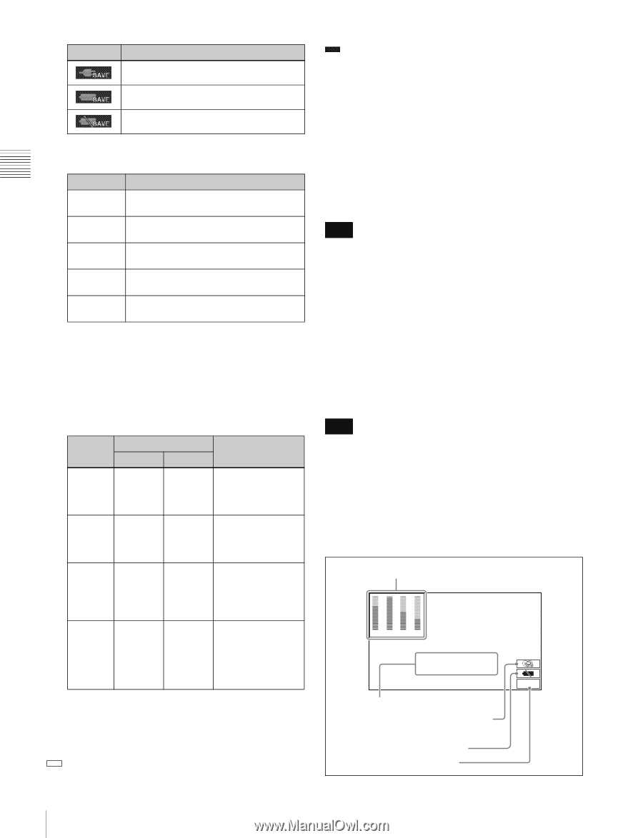
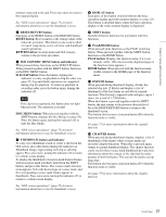
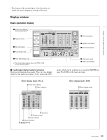
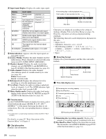
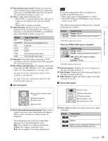
Chapter 2 Names and Functions of Parts Display Power status AC power (power-saving mode) Battery (power-saving mode) Battery (power-saving mode/low) B Menu setting status: Displays the current setting status of setup menu. Display BANK1 Description The current menu settings are the same as the settings in menu bank 1. BANK2 BANK3 DEFAULT No display The current menu settings are the same as the settings in menu bank 2. The current menu settings are the same as the settings in menu bank 3. The current menu settings are the same as the factory defaults. The current menu settings are different from all of the above. C Remote interface: When the remote control switch is set to REMOTE, displays the name of the interface selected with setup menu item 214 REMOTE INTERFACE. D Clip playback mode: The clip playback mode appears as follows, according to the settings of setup menu items 142 REPEAT MODE and 154 SINGLE CLIP PLAY MODE. Display REPEAT SINGLE SNGL RPT No display Setup menu setting Item 142 Item 154 "play & off VAR fwd" or "force" off on "play & on VAR fwd" or "force" off off Description Repeat playback mode: Perform repeat playback of all clips on the disc. Single clip playback mode: Play the currently selected clip once. Single clip repeat playback mode: Play the currently selected clip repeatedly. Continuous playback mode: Perform continuous playback of all clips on the disc, playing each clip once. E Jog/shuttle dial mode: Appears when the unit is in shuttle, jog, or variable mode. h Format conversion This displays the status of 1080/720 format conversion. : Format conversion is not being performed. FC : Format conversion is being performed. See page 64 for more information about 1080/720 cross convert function. i Reference signal This displays the type of reference signal to which this unit is synchronizing. When there is no display, the unit is synchronizing to the internal reference signal. INPUT: Input video HD REF: HD-format reference signal SD REF: SD-format reference signal Note The HD REF or SD REF display flashes when the video input signal is not synchronized to the reference signal, and when the signals are synchronized but their phases do not match. j Video input display This displays the currently selected video input signal. HDSDI: HDSDI video input SDSDI: SDSDI video input i.LINK: i.LINK TS (HDV) input 1) SG: Test video signal from the internal signal generator 1) When the PDBK-201 option board is installed Note The display blinks when there is no video input signal, and when the video input signal does not match the system frequency of this unit. The video signal input is selected with V INPUT on page P1 VIDEO of the function menu (see page 49). Video monitor display A Audio level meters 0 -10 -20 -30 -40 -60 12 0 -10 -20 -30 -40 -60 34 TCR.00:45.39.18* JOG STILL B Superimposed information C Recording mode indication D Low battery warning E Converter display DC-SQ 26 Front Panel
-
 1
1 -
2
-
3
-
4
-
5
-
6
-
7
-
8
-
9
-
10
-
11
-
12
-
13
-
14
-
15
-
16
-
17
-
18
-
19
-
20
-
 21
21 -
 22
22 -
 23
23 -
 24
24 -
 25
25 -
 26
26 -
 27
27 -
 28
28 -
 29
29 -
 30
30 -
 31
31 -
32
-
33
-
34
-
35
-
36
-
37
-
38
-
39
-
40
-
41
-
42
-
43
-
44
-
45
-
46
-
47
-
48
-
49
-
50
-
51
-
52
-
53
-
54
-
55
-
56
-
57
-
58
-
59
-
60
-
61
-
62
-
63
-
64
-
65
-
66
-
67
-
68
-
69
-
70
-
71
-
72
-
73
-
74
-
75
-
76
-
77
-
78
-
79
-
80
-
81
-
82
-
83
-
84
-
85
-
86
-
87
-
88
-
89
-
90
-
91
-
92
-
93
-
94
-
95
-
96
-
97
-
98
-
99
-
100
-
101
-
102
-
103
-
104
-
105
-
106
-
107
-
108
-
109
-
110
-
111
-
112
-
113
-
114
-
115
-
116
-
117
-
118
-
119
-
120
-
121
-
122
-
123
-
124
-
125
-
126
-
127
-
128
-
129
-
130
-
131
-
132
-
133
-
134
-
135
-
136
-
137
-
138
-
139
-
140
-
141
-
142
-
143
-
144
-
145
-
146
-
147
-
148
-
149
-
150
-
151
-
152
-
153
-
154
-
155
-
156
-
157
-
158
-
159
-
160
-
161
-
162
-
163
-
164
-
165
-
166
-
167
-
168
-
169
-
170
-
171
-
172
-
173
-
174
-
175
-
176
-
177
-
178
-
179
-
180
-
181
-
182
-
183
-
184
-
185
-
186
-
187
-
188
-
189
-
190
-
191
-
192
-
193
-
194
-
195
-
196
-
197
-
198
 |
 |