Sony PDWHD1500 User Manual (PDW-HD1500 / PDW-F1600 Operation Manual for Firmwa - Page 46
Timecode generator drop-frame mark for 59.94i
 |
View all Sony PDWHD1500 manuals
Add to My Manuals
Save this manual to your list of manuals |
Page 46 highlights
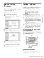
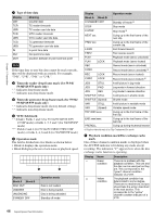
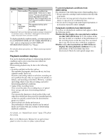
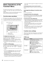
Chapter 3 Preparations a Type of time data Display CNT TCR Meaning Counter data TC reader timecode UBR TCR. UBR. TC reader user bits data VITC reader timecode VITC reader user bits data TCG UBG IN TC generator timecode TC generator user bits data In point time data OUT DUR Out point time data Duration between In point and Out point Note If the time data or user bits data cannot be read correctly, they will be displayed with an asterisk. For example, "T*R", "U*R", "T*R." or "U*R.". b Timecode reader drop-frame mark (for 59.94i/ 59.94P/29.97P mode only) ".": Indicates drop-frame mode. ":": Indicates non-drop-frame mode. c Timecode generator drop-frame mark (for 59.94i/ 59.94P/29.97P mode only) ".": Indicates drop-frame mode (factory default setting). ":": Indicates non-drop-frame mode. d VITC field mark " " (blank): Fields 1 and 3 (for 59.94i/59.94P/29.97P/ 23.98P mode) or fields 1, 3, 5 and 7 (for 50i/50P/25P mode) "*": Fields 2 and 4 (for 59.94i/59.94P/29.97P/23.98P mode) or fields 2, 4, 6 and 8 (for 50i/50P/25P mode) e Operation mode The field is divided into two blocks as shown below. • Block A displays the operation mode. • Block B displays the servo lock status or playback speed. A B Display Block A Block B DISC OUT LOADING UNLOADING STANDBY OFF Operation mode Disc is not loaded. Disc is being loaded. Disc is being unloaded. Standby off mode Display Operation mode Block A Block B C.STANDBY OFF Standby off mode a) STOP Stop mode C.STOP Stop mode a) NEXT xxx Cuing up to the first frame of the next clip. PREV xxx Cuing up to the first frame of the current clip. F.FWD Fast forward search F.REV Fast reverse search PLAY Playback mode (servo unlocked) PLAY LOCK Playback mode (servo locked) REC Record mode (servo unlocked) C.REC Record mode (servo unlocked) a) REC LOCK Record mode (servo locked) C.REC LOCK Record mode (servo locked) a) JOG STILL A still picture in jog mode JOG FWD Jog mode in forward direction JOG REV Jog mode in reverse direction SHUTTLE STILL A still picture in shuttle mode SHUTTLE (Speed) Shuttle mode VAR STILL A still picture in variable mode VAR (Speed) Variable speed mode TOP 0001/xxxx Cuing up to the first frame of the first clip. END xxxx/xxxx Cuing up to the last frame of the last clip. PREROLL Cuing up during thumbnail search a) Display when the unit is in Clip Continuous Rec mode. f Playback condition mark/Disc exchange cache mark One of three channel condition marks is displayed when the ACCESS indicator is lit during any mode except recording. The indication "C" appears here when the disc exchange cache function is operating. Display Name Green condition Yellow condition Description There is no problem with the playback condition. This unit and the disc can be used just as they are. This corresponds to the "green" channel condition indicator of a VTR. The playback condition has deteriorated to some degree. There are no read errors, but you should take the action described in the next section. This corresponds to the "yellow" channel condition indicator of a VTR. 46 Superimposed Text Information
-
 1
1 -
2
-
3
-
4
-
5
-
6
-
7
-
8
-
9
-
10
-
11
-
12
-
13
-
14
-
15
-
16
-
17
-
18
-
19
-
20
-
21
-
22
-
23
-
24
-
25
-
26
-
27
-
28
-
29
-
30
-
31
-
32
-
33
-
34
-
35
-
36
-
37
-
38
-
39
-
40
-
 41
41 -
 42
42 -
 43
43 -
 44
44 -
 45
45 -
 46
46 -
 47
47 -
 48
48 -
 49
49 -
 50
50 -
 51
51 -
52
-
53
-
54
-
55
-
56
-
57
-
58
-
59
-
60
-
61
-
62
-
63
-
64
-
65
-
66
-
67
-
68
-
69
-
70
-
71
-
72
-
73
-
74
-
75
-
76
-
77
-
78
-
79
-
80
-
81
-
82
-
83
-
84
-
85
-
86
-
87
-
88
-
89
-
90
-
91
-
92
-
93
-
94
-
95
-
96
-
97
-
98
-
99
-
100
-
101
-
102
-
103
-
104
-
105
-
106
-
107
-
108
-
109
-
110
-
111
-
112
-
113
-
114
-
115
-
116
-
117
-
118
-
119
-
120
-
121
-
122
-
123
-
124
-
125
-
126
-
127
-
128
-
129
-
130
-
131
-
132
-
133
-
134
-
135
-
136
-
137
-
138
-
139
-
140
-
141
-
142
-
143
-
144
-
145
-
146
-
147
-
148
-
149
-
150
-
151
-
152
-
153
-
154
-
155
-
156
-
157
-
158
-
159
-
160
-
161
-
162
-
163
-
164
-
165
-
166
-
167
-
168
-
169
-
170
-
171
-
172
-
173
-
174
-
175
-
176
-
177
-
178
-
179
-
180
-
181
-
182
-
183
-
184
-
185
-
186
-
187
-
188
-
189
-
190
-
191
-
192
-
193
-
194
-
195
-
196
-
197
-
198
 |
 |