TP-Link T3700G-28TQ T3700G-28TQ V1 UG - Page 179
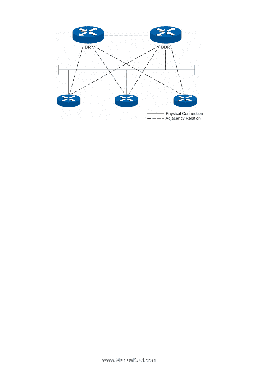
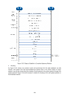
OSPF Working Process, Diagram of DR/BDR Adjacency Relation
 |
View all TP-Link T3700G-28TQ manuals
Add to My Manuals
Save this manual to your list of manuals |
Page 179 highlights
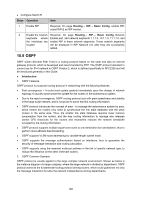
Figure 10-30 Diagram of DR/BDR Adjacency Relation DR or BDR is determined by the interface priority and router ID. First of all, whether a router could be the DR or BDR on a network is decided by its interface priority. The one of highest priority would be elected as DR or BDR; while if all the interfaces are of the same priority, it would then be decided by the router ID. In conclusion, DR or BDR is the feature of a certain interface of the router which indicates the status of the router in a network segment rather than the features of the router on the network. Every network segment needs to elect a DR and a BDR to synchronize the routing information. The configuration of router interface parameters needs to be done on the basis of network planning. OSPF Working Process In the following, we would take the example of two routers initiating interface OSPF protocol to introduce the working process of OSPF routing protocol in the Ethernet model. 1) The router interface initiates the OSPF protocol, and then the interfaces in the same network segment would discover neighbors by sending Hello packets. If the interfaces are connected on the same public data link, and the area IDs, authentication information, network subnet, Hello data interval and neighbor router dead-interval are all matched, the two routers would put each other in its neighbor table. 2) If the receiver discovers its own ID on the neighbor table of the Hello packet, a successful mutual communication would be established. And then they will elect DR and BDR according to such parameters as the interface priority and the router ID, while if DR and BDR already exist in the network, they will be accepted. 3) After DR and BDR are determined, the master and slave one will be elected between the DR/BDR and the other routers on the network, and then the link state database synchronization will start. 4) On the network the routers and DR/BDR will mutually unicast the link state data to advertise LSA, until all the routers establish an identical link state database. During the synchronization of link state database, if the database description packet sent contains an updated LSA or a LSA the receiver doesn't have, the receiver would send request for the details of this LSA via LSR packets. In other words, in any phase of DD exchange, as long as the received DD packet contains new LSA information, the receiver could send LSA request for synchronization. The routers receiving the LSR packet will unicast the LSU packet carrying LSA to the other end. 168
-
 1
1 -
2
-
3
-
4
-
5
-
6
-
7
-
8
-
9
-
10
-
11
-
12
-
13
-
14
-
15
-
16
-
17
-
18
-
19
-
20
-
21
-
22
-
23
-
24
-
25
-
26
-
27
-
28
-
29
-
30
-
31
-
32
-
33
-
34
-
35
-
36
-
37
-
38
-
39
-
40
-
41
-
42
-
43
-
44
-
45
-
46
-
47
-
48
-
49
-
50
-
51
-
52
-
53
-
54
-
55
-
56
-
57
-
58
-
59
-
60
-
61
-
62
-
63
-
64
-
65
-
66
-
67
-
68
-
69
-
70
-
71
-
72
-
73
-
74
-
75
-
76
-
77
-
78
-
79
-
80
-
81
-
82
-
83
-
84
-
85
-
86
-
87
-
88
-
89
-
90
-
91
-
92
-
93
-
94
-
95
-
96
-
97
-
98
-
99
-
100
-
101
-
102
-
103
-
104
-
105
-
106
-
107
-
108
-
109
-
110
-
111
-
112
-
113
-
114
-
115
-
116
-
117
-
118
-
119
-
120
-
121
-
122
-
123
-
124
-
125
-
126
-
127
-
128
-
129
-
130
-
131
-
132
-
133
-
134
-
135
-
136
-
137
-
138
-
139
-
140
-
141
-
142
-
143
-
144
-
145
-
146
-
147
-
148
-
149
-
150
-
151
-
152
-
153
-
154
-
155
-
156
-
157
-
158
-
159
-
160
-
161
-
162
-
163
-
164
-
165
-
166
-
167
-
168
-
169
-
170
-
171
-
172
-
173
-
 174
174 -
 175
175 -
 176
176 -
 177
177 -
 178
178 -
 179
179 -
 180
180 -
 181
181 -
 182
182 -
 183
183 -
 184
184 -
185
-
186
-
187
-
188
-
189
-
190
-
191
-
192
-
193
-
194
-
195
-
196
-
197
-
198
-
199
-
200
-
201
-
202
-
203
-
204
-
205
-
206
-
207
-
208
-
209
-
210
-
211
-
212
-
213
-
214
-
215
-
216
-
217
-
218
-
219
-
220
-
221
-
222
-
223
-
224
-
225
-
226
-
227
-
228
-
229
-
230
-
231
-
232
-
233
-
234
-
235
-
236
-
237
-
238
-
239
-
240
-
241
-
242
-
243
-
244
-
245
-
246
-
247
-
248
-
249
-
250
-
251
-
252
-
253
-
254
-
255
-
256
-
257
-
258
-
259
-
260
-
261
-
262
-
263
-
264
-
265
-
266
-
267
-
268
-
269
-
270
-
271
-
272
-
273
-
274
-
275
-
276
-
277
-
278
-
279
-
280
-
281
-
282
-
283
-
284
-
285
-
286
-
287
-
288
-
289
-
290
-
291
-
292
-
293
-
294
-
295
-
296
-
297
-
298
-
299
-
300
-
301
-
302
-
303
-
304
-
305
-
306
-
307
-
308
-
309
-
310
-
311
-
312
-
313
-
314
-
315
-
316
-
317
-
318
-
319
-
320
-
321
-
322
-
323
-
324
-
325
-
326
-
327
-
328
-
329
-
330
-
331
-
332
-
333
-
334
-
335
-
336
-
337
-
338
-
339
-
340
-
341
-
342
-
343
-
344
-
345
-
346
-
347
-
348
-
349
-
350
-
351
-
352
-
353
-
354
-
355
-
356
-
357
-
358
-
359
-
360
-
361
-
362
-
363
-
364
-
365
-
366
-
367
-
368
-
369
-
370
-
371
-
372
-
373
-
374
-
375
-
376
-
377
-
378
-
379
-
380
-
381
-
382
-
383
-
384
-
385
-
386
-
387
-
388
-
389
-
390
-
391
-
392
-
393
-
394
-
395
-
396
 |
 |