TP-Link T3700G-28TQ T3700G-28TQ V1 UG - Page 183
classified into 4 types: Internal Router IR, Backbone Router BR, Area Boundary Router ABR, Router
 |
View all TP-Link T3700G-28TQ manuals
Add to My Manuals
Save this manual to your list of manuals |
Page 183 highlights
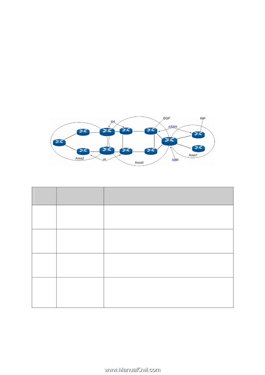
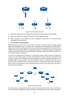
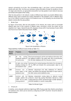
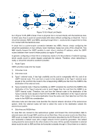
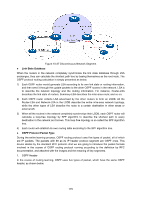
network connectivity at all time. The non-backbone Area 1 and Area 2 cannot communicate directly with each other, but they can exchange routing information through the backbone Area 0. On large-scale networks, an appropriate area partition can help greatly to save network resources and enhance the speed of the routing. After the area partition in the network, routers of different type need to accomplish different tasks. Different areas need to transmit the routing information to the backbone area in different ways, due to their different locations relative to the backbone area. In the following, we will introduce the details involved after the area partition. 1. Router Type As Figure 10-34 shows, after the area partition of the network, the routers need to accomplish different tasks due to their locations in different areas, according to which the routers can be classified into 4 types: Internal Router (IR), Backbone Router (BR), Area Boundary Router (ABR) and Autonomous System Boundary Router (ASBR). Figure 10-34 Classification of Routers Responsibilities of different routers divide as Table 10-2. Router Name Features Responsibility IR All the routing Flood and exchange its all link and interface information with interfaces belong to the adjacent routers in the same area, thus to synchronize the same area the link state database with the intra-area routers. BR At least one routing Summarize the routing topology information from all areas in interface belongs to AS via ABR and forward the communication data for all the backbone area areas. ABR Connect one or Maintain independent link state databases for different more areas to the areas, and deliver the topology information of each area to backbone area the other areas via the backbone area. ASBR Connect with the routers outside the OSPF AS by other routing protocol Maintain independent routing tables for different routing protocols, import the routing information learned by other routing protocol to OSPF domain through a certain standard, and then establish a uniform routing table. Table 10-2 Router Types 2. Virtual Link In practice, some physical restrictions might keep ABR of some areas from directly connecting to the backbone area, which can be solved by configuring an OSPF virtual link. Virtual link sketch is shown as below. 172
-
 1
1 -
2
-
3
-
4
-
5
-
6
-
7
-
8
-
9
-
10
-
11
-
12
-
13
-
14
-
15
-
16
-
17
-
18
-
19
-
20
-
21
-
22
-
23
-
24
-
25
-
26
-
27
-
28
-
29
-
30
-
31
-
32
-
33
-
34
-
35
-
36
-
37
-
38
-
39
-
40
-
41
-
42
-
43
-
44
-
45
-
46
-
47
-
48
-
49
-
50
-
51
-
52
-
53
-
54
-
55
-
56
-
57
-
58
-
59
-
60
-
61
-
62
-
63
-
64
-
65
-
66
-
67
-
68
-
69
-
70
-
71
-
72
-
73
-
74
-
75
-
76
-
77
-
78
-
79
-
80
-
81
-
82
-
83
-
84
-
85
-
86
-
87
-
88
-
89
-
90
-
91
-
92
-
93
-
94
-
95
-
96
-
97
-
98
-
99
-
100
-
101
-
102
-
103
-
104
-
105
-
106
-
107
-
108
-
109
-
110
-
111
-
112
-
113
-
114
-
115
-
116
-
117
-
118
-
119
-
120
-
121
-
122
-
123
-
124
-
125
-
126
-
127
-
128
-
129
-
130
-
131
-
132
-
133
-
134
-
135
-
136
-
137
-
138
-
139
-
140
-
141
-
142
-
143
-
144
-
145
-
146
-
147
-
148
-
149
-
150
-
151
-
152
-
153
-
154
-
155
-
156
-
157
-
158
-
159
-
160
-
161
-
162
-
163
-
164
-
165
-
166
-
167
-
168
-
169
-
170
-
171
-
172
-
173
-
174
-
175
-
176
-
177
-
 178
178 -
 179
179 -
 180
180 -
 181
181 -
 182
182 -
 183
183 -
 184
184 -
 185
185 -
 186
186 -
 187
187 -
 188
188 -
189
-
190
-
191
-
192
-
193
-
194
-
195
-
196
-
197
-
198
-
199
-
200
-
201
-
202
-
203
-
204
-
205
-
206
-
207
-
208
-
209
-
210
-
211
-
212
-
213
-
214
-
215
-
216
-
217
-
218
-
219
-
220
-
221
-
222
-
223
-
224
-
225
-
226
-
227
-
228
-
229
-
230
-
231
-
232
-
233
-
234
-
235
-
236
-
237
-
238
-
239
-
240
-
241
-
242
-
243
-
244
-
245
-
246
-
247
-
248
-
249
-
250
-
251
-
252
-
253
-
254
-
255
-
256
-
257
-
258
-
259
-
260
-
261
-
262
-
263
-
264
-
265
-
266
-
267
-
268
-
269
-
270
-
271
-
272
-
273
-
274
-
275
-
276
-
277
-
278
-
279
-
280
-
281
-
282
-
283
-
284
-
285
-
286
-
287
-
288
-
289
-
290
-
291
-
292
-
293
-
294
-
295
-
296
-
297
-
298
-
299
-
300
-
301
-
302
-
303
-
304
-
305
-
306
-
307
-
308
-
309
-
310
-
311
-
312
-
313
-
314
-
315
-
316
-
317
-
318
-
319
-
320
-
321
-
322
-
323
-
324
-
325
-
326
-
327
-
328
-
329
-
330
-
331
-
332
-
333
-
334
-
335
-
336
-
337
-
338
-
339
-
340
-
341
-
342
-
343
-
344
-
345
-
346
-
347
-
348
-
349
-
350
-
351
-
352
-
353
-
354
-
355
-
356
-
357
-
358
-
359
-
360
-
361
-
362
-
363
-
364
-
365
-
366
-
367
-
368
-
369
-
370
-
371
-
372
-
373
-
374
-
375
-
376
-
377
-
378
-
379
-
380
-
381
-
382
-
383
-
384
-
385
-
386
-
387
-
388
-
389
-
390
-
391
-
392
-
393
-
394
-
395
-
396
 |
 |