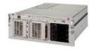
Compaq DL580R01 Service Guide - Page 178
PCI Hot Plug LED switchboard, PCI Hot Plug slots
 |
UPC - 720591221416
View all Compaq DL580R01 manuals
Add to My Manuals
Save this manual to your list of manuals |
Page 178 highlights
bezel, front LED indicators function 4-12 identifying status and conditions 4-12 illustrated 4-12 part number 1-3 removing 2-11 removing, illustrated 2-11 replacing 2-11 board in use by expand operation 3-36 board not attached 3-36 C cable clips, part number 1-7 cables 10-position PS and MB power, part number 1-6 12-position PS and MB power, part number 1-6 AC power connectors, identified 4-5 part number 1-6 removing 2-47 removing ground wire screw 2-48 removing, illustrated 2-47, 2-49 replacing 2-49 unplugging from power backplane board 2-48 ADU error messages 3-41 caution 2-20 data cable assembly, PS and MB, part number 1-7 diskette drive data cable assembly, part number 1-7 diskette/LVD power, part number 1-6 internal/external VHDCI cable, part number 1-7 miscellaneous signal, part number 1-7 PCI Hot Plug LED switchboard connector, identified 4-3 part number 1-6 removing 2-42 removing, illustrated 2-42 replacing 2-42 routing diagrams 2-20 cautions ADU 3-33 airflow 2-24 Index 3 appropriate device drivers, installed 2-36 battery handling and disposal 2-52 battery replacement 2-52 BIOS settings 2-52 controller firmware upgrade 3-33 data loss 2-16, 3-5 defined vii Erase Utility 3-5 firmware upgrade 3-33 grounding viii hard drive replacement 2-16 opening slot release levers 2-36 overheating viii, 2-7, 2-24 PCI Hot Plug slots 2-38 PCI Hot Plug support 2-36 peripheral board release levers 2-28 power fluctuations 2-7 power supply removal 2-24 power, removing from system 2-28 ROM core frequency determination 4-9 routing cables 2-20 slot release lever 2-38 switches are pre-set, nonadjustable 4-10 system board removal 2-45 UPS 2-7 ventilation clearances viii CD-ROM drive location 2-14 part number 1-6 position, identified 2-14 removing 2-17, 2-19 removing, illustrated 2-17, 2-19 replacing 2-17, 2-19 signal cables, part number 1-7 specifications 5-6 test error codes 3-31 CD-ROM signal and power cables, routing diagram 2-20 center wall part number 1-3 removing 2-33 removing, illustrated 2-33 replacing 2-33 chassis, part number 1-3 CMOS, clearing 4-8 communication parameters, setting 3-64 Compaq authorized reseller ix Compaq Insight Manager
-
 1
1 -
2
-
3
-
4
-
5
-
6
-
7
-
8
-
9
-
10
-
11
-
12
-
13
-
14
-
15
-
16
-
17
-
18
-
19
-
20
-
21
-
22
-
23
-
24
-
25
-
26
-
27
-
28
-
29
-
30
-
31
-
32
-
33
-
34
-
35
-
36
-
37
-
38
-
39
-
40
-
41
-
42
-
43
-
44
-
45
-
46
-
47
-
48
-
49
-
50
-
51
-
52
-
53
-
54
-
55
-
56
-
57
-
58
-
59
-
60
-
61
-
62
-
63
-
64
-
65
-
66
-
67
-
68
-
69
-
70
-
71
-
72
-
73
-
74
-
75
-
76
-
77
-
78
-
79
-
80
-
81
-
82
-
83
-
84
-
85
-
86
-
87
-
88
-
89
-
90
-
91
-
92
-
93
-
94
-
95
-
96
-
97
-
98
-
99
-
100
-
101
-
102
-
103
-
104
-
105
-
106
-
107
-
108
-
109
-
110
-
111
-
112
-
113
-
114
-
115
-
116
-
117
-
118
-
119
-
120
-
121
-
122
-
123
-
124
-
125
-
126
-
127
-
128
-
129
-
130
-
131
-
132
-
133
-
134
-
135
-
136
-
137
-
138
-
139
-
140
-
141
-
142
-
143
-
144
-
145
-
146
-
147
-
148
-
149
-
150
-
151
-
152
-
153
-
154
-
155
-
156
-
157
-
158
-
159
-
160
-
161
-
162
-
163
-
164
-
165
-
166
-
167
-
168
-
169
-
170
-
171
-
172
-
 173
173 -
 174
174 -
 175
175 -
 176
176 -
 177
177 -
 178
178 -
 179
179 -
 180
180 -
 181
181 -
 182
182 -
 183
183 -
184
-
185
-
186
-
187
-
188
-
189
-
190
-
191
-
192
-
193
 |
 |
