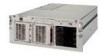
Compaq DL580R01 Service Guide - Page 183
Wide Ultra2/Ultra3 hard drive, Power On/Standby switch
 |
UPC - 720591221416
View all Compaq DL580R01 manuals
Add to My Manuals
Save this manual to your list of manuals |
Page 183 highlights
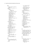
8 Compaq ProLiant DL580 Server Maintenance and Service Guide unplugging from power backplane board 2-48 AC power supply connector, removing 2-49 battery installation 2-53 bezel, removing 2-11 cable routing CD-ROM signal and power 2-20 diskette drive signal and power 2-20 peripheral board 2-23 power backplane board 2-22 power switch 2-21 CD-ROM drive LEDs 4-20 removing 2-19 center wall, removing 2-33 DIMMs, removing 2-32 diskette drive LEDs 4-20 removing 2-18 exploded view mechanical parts 1-2 system components 1-4 fans LEDs 4-12 locations 2-12 removing 2-13 front bezel LEDs 4-12 hard drives locations 2-14 removing 2-16 hot-plug fan locations and LED indicators 4-16 hot-plug hard drive LED indicators 4-19 LED indicators replacement conditions 4-19 hot-plug power supply LEDs 4-15 removing 2-24 Integrated Smart Array Controller, removing 2-51 Internal Diagnostics Display (IDD) 4-14 media storage devices 2-14 memory board, removing 2-31 LEDs 4-12 socket locations 2-29 network interface card (NIC), removing 2-39 PCI guide bracket, removing 2-43 PCI Hot Plug access door, opening 2-37 basket insulator, removing 2-41 buttons, location 2-38 expansion board, removing 2-39 LED switchboard and cable, removing 2-42 switchboard LEDs 4-17 peripheral board configuration switch 4-7 connectors 4-4 removing 2-28 power backplane board connectors 4-5 removing 2-44 power cord and plug, removing 2-49 Power On/Standby switch disconnecting 2-9 removing 2-10 power supply cables, removing 2-47 power switch, LEDs 4-12 processor cage, removing 2-46 processor terminator module, removing 2-27 processors core frequency switch (SW4) 4-9 removing 2-26 terminator module, locations 2-25 terminator module, removing 2-27 rear panel components 4-2 removable media device, removing 2-17 SCSI hard drive backplane board connectors 4-6 removing 2-34 system board connectors 4-3 ID/miscellaneous switches (SW6) 4-10 removing 2-45 system interlock LEDs 4-13 top access panel, removing 2-8 Wide Ultra2/Ultra3 hard drive cage, removing 2-35 IML See also Critical Error Log accessing from Compaq Insight Manager 3-53 defined 3-53, 3-68 description 3-3
-
 1
1 -
2
-
3
-
4
-
5
-
6
-
7
-
8
-
9
-
10
-
11
-
12
-
13
-
14
-
15
-
16
-
17
-
18
-
19
-
20
-
21
-
22
-
23
-
24
-
25
-
26
-
27
-
28
-
29
-
30
-
31
-
32
-
33
-
34
-
35
-
36
-
37
-
38
-
39
-
40
-
41
-
42
-
43
-
44
-
45
-
46
-
47
-
48
-
49
-
50
-
51
-
52
-
53
-
54
-
55
-
56
-
57
-
58
-
59
-
60
-
61
-
62
-
63
-
64
-
65
-
66
-
67
-
68
-
69
-
70
-
71
-
72
-
73
-
74
-
75
-
76
-
77
-
78
-
79
-
80
-
81
-
82
-
83
-
84
-
85
-
86
-
87
-
88
-
89
-
90
-
91
-
92
-
93
-
94
-
95
-
96
-
97
-
98
-
99
-
100
-
101
-
102
-
103
-
104
-
105
-
106
-
107
-
108
-
109
-
110
-
111
-
112
-
113
-
114
-
115
-
116
-
117
-
118
-
119
-
120
-
121
-
122
-
123
-
124
-
125
-
126
-
127
-
128
-
129
-
130
-
131
-
132
-
133
-
134
-
135
-
136
-
137
-
138
-
139
-
140
-
141
-
142
-
143
-
144
-
145
-
146
-
147
-
148
-
149
-
150
-
151
-
152
-
153
-
154
-
155
-
156
-
157
-
158
-
159
-
160
-
161
-
162
-
163
-
164
-
165
-
166
-
167
-
168
-
169
-
170
-
171
-
172
-
173
-
174
-
175
-
176
-
177
-
 178
178 -
 179
179 -
 180
180 -
 181
181 -
 182
182 -
 183
183 -
 184
184 -
 185
185 -
 186
186 -
 187
187 -
 188
188 -
189
-
190
-
191
-
192
-
193
 |
 |
