Compaq DL580R01 Service Guide - Page 184
Power On/Standby switch, part, PCI Hot Plug switchboard
 |
UPC - 720591221416
View all Compaq DL580R01 manuals
Add to My Manuals
Save this manual to your list of manuals |
Page 184 highlights
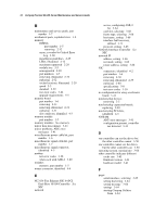
error types, explained 3-68 security levels defined 3-53 viewing 3-53, 3-54, 3-68 Insight Agents, defined 3-76 Insight Management Agents, enabling 3-58 INSPECT accessing 3-2 description 3-2, 3-4 listing, printing 3-4 running 3-4 starting remotely 3-66 insufficient adapter resources 3-39 insufficient battery voltage 3-39 Integrated Management Log See IML Integrated Remote Console, features 3-61 integrated server management, features 3-58 Integrated Smart Array Controller cache size 5-9 connector, identified 4-4 data transfer method 5-9 features 2-50 illustrated 2-51 maximum drives supported 5-9 part number 1-6 protocol 5-9 removing 2-51 replacing 2-51 SCSI port connectors 5-9 specifications 5-9 transfer rate 5-9 inter-controller link connection could not be established 3-39 interlock LEDs See system interlock LEDs Internal Diagnostics Display (IDD) function 4-14 identifying codes 4-14 illustrated 4-14 indicator codes 4-15 locating 4-14 IP access 3-64 IP/IPX, using network features 3-60 IRQ conflict, resolving 3-3 J jumper settings, obtaining 3-3 K keyboard connector, identified 4-4 Index 9 controller error 3-10 POST error messages 3-10 test error codes 3-25 kits country kit (rack), part number 1-7 power cable kit, part number 1-6 rack mounting kit, part number 1-7 return kit, part number 1-7 signal cable kit, part number 1-7 L labels symbols on equipment 2-3 LED power switch connector, identified 4-5 LEDs diskette drive and CD-ROM 4-20 fans 4-12 hot-plug hard drive 4-19 hot-plug hard drive LED indicators 4-19 memory 4-12 PCI Hot Plug board status 4-17 PCI Hot Plug switchboard illustrated 4-17 Power On/Standby switch, part number 1-5 power supply explained 4-15 overview 4-15 power switch 4-12 logical drive problems, ADU error messages 3-40 logical drive X failed due to cache error 3-40 status = failed 3-40 status = interim recovery 3-40 status = loose cable detected 3-40 status = overheated 3-40 status = overheating 3-40 status = recovering 3-40 status = wrong drive replaced 3-41 loose cable detected-logical drives may be marked FAILED until corrected 3-41
-
 1
1 -
2
-
3
-
4
-
5
-
6
-
7
-
8
-
9
-
10
-
11
-
12
-
13
-
14
-
15
-
16
-
17
-
18
-
19
-
20
-
21
-
22
-
23
-
24
-
25
-
26
-
27
-
28
-
29
-
30
-
31
-
32
-
33
-
34
-
35
-
36
-
37
-
38
-
39
-
40
-
41
-
42
-
43
-
44
-
45
-
46
-
47
-
48
-
49
-
50
-
51
-
52
-
53
-
54
-
55
-
56
-
57
-
58
-
59
-
60
-
61
-
62
-
63
-
64
-
65
-
66
-
67
-
68
-
69
-
70
-
71
-
72
-
73
-
74
-
75
-
76
-
77
-
78
-
79
-
80
-
81
-
82
-
83
-
84
-
85
-
86
-
87
-
88
-
89
-
90
-
91
-
92
-
93
-
94
-
95
-
96
-
97
-
98
-
99
-
100
-
101
-
102
-
103
-
104
-
105
-
106
-
107
-
108
-
109
-
110
-
111
-
112
-
113
-
114
-
115
-
116
-
117
-
118
-
119
-
120
-
121
-
122
-
123
-
124
-
125
-
126
-
127
-
128
-
129
-
130
-
131
-
132
-
133
-
134
-
135
-
136
-
137
-
138
-
139
-
140
-
141
-
142
-
143
-
144
-
145
-
146
-
147
-
148
-
149
-
150
-
151
-
152
-
153
-
154
-
155
-
156
-
157
-
158
-
159
-
160
-
161
-
162
-
163
-
164
-
165
-
166
-
167
-
168
-
169
-
170
-
171
-
172
-
173
-
174
-
175
-
176
-
177
-
178
-
 179
179 -
 180
180 -
 181
181 -
 182
182 -
 183
183 -
 184
184 -
 185
185 -
 186
186 -
 187
187 -
 188
188 -
 189
189 -
190
-
191
-
192
-
193
 |
 |
