HP 5550dn HP Color LaserJet 5550 series - User Guide - Page 260
Align the formatter board in the tracks at the top and bottom of the slot, and then slide
 |
UPC - 829160126913
View all HP 5550dn manuals
Add to My Manuals
Save this manual to your list of manuals |
Page 260 highlights
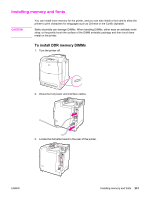
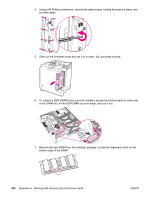
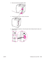
5. Slide out the formatter board and set it on a clean, flat, grounded surface. 6. Align the groove on the side of the flash memory card with the notches in the connector and push it in the slot until it is fully seated. CAUTION Note Do not insert the flash memory card at an angle. The first flash memory slot marked "Firmware Slot" is reserved for firmware only. Slots 2 and 3 should be used for all other solutions. 7. Align the formatter board in the tracks at the top and bottom of the slot, and then slide the board back into the printer. Replace and tighten the eight screws removed in step 4. 246 Appendix A Working with memory and print server cards ENWW
-
 1
1 -
2
-
3
-
4
-
5
-
6
-
7
-
8
-
9
-
10
-
11
-
12
-
13
-
14
-
15
-
16
-
17
-
18
-
19
-
20
-
21
-
22
-
23
-
24
-
25
-
26
-
27
-
28
-
29
-
30
-
31
-
32
-
33
-
34
-
35
-
36
-
37
-
38
-
39
-
40
-
41
-
42
-
43
-
44
-
45
-
46
-
47
-
48
-
49
-
50
-
51
-
52
-
53
-
54
-
55
-
56
-
57
-
58
-
59
-
60
-
61
-
62
-
63
-
64
-
65
-
66
-
67
-
68
-
69
-
70
-
71
-
72
-
73
-
74
-
75
-
76
-
77
-
78
-
79
-
80
-
81
-
82
-
83
-
84
-
85
-
86
-
87
-
88
-
89
-
90
-
91
-
92
-
93
-
94
-
95
-
96
-
97
-
98
-
99
-
100
-
101
-
102
-
103
-
104
-
105
-
106
-
107
-
108
-
109
-
110
-
111
-
112
-
113
-
114
-
115
-
116
-
117
-
118
-
119
-
120
-
121
-
122
-
123
-
124
-
125
-
126
-
127
-
128
-
129
-
130
-
131
-
132
-
133
-
134
-
135
-
136
-
137
-
138
-
139
-
140
-
141
-
142
-
143
-
144
-
145
-
146
-
147
-
148
-
149
-
150
-
151
-
152
-
153
-
154
-
155
-
156
-
157
-
158
-
159
-
160
-
161
-
162
-
163
-
164
-
165
-
166
-
167
-
168
-
169
-
170
-
171
-
172
-
173
-
174
-
175
-
176
-
177
-
178
-
179
-
180
-
181
-
182
-
183
-
184
-
185
-
186
-
187
-
188
-
189
-
190
-
191
-
192
-
193
-
194
-
195
-
196
-
197
-
198
-
199
-
200
-
201
-
202
-
203
-
204
-
205
-
206
-
207
-
208
-
209
-
210
-
211
-
212
-
213
-
214
-
215
-
216
-
217
-
218
-
219
-
220
-
221
-
222
-
223
-
224
-
225
-
226
-
227
-
228
-
229
-
230
-
231
-
232
-
233
-
234
-
235
-
236
-
237
-
238
-
239
-
240
-
241
-
242
-
243
-
244
-
245
-
246
-
247
-
248
-
249
-
250
-
251
-
252
-
253
-
254
-
 255
255 -
 256
256 -
 257
257 -
 258
258 -
 259
259 -
 260
260 -
 261
261 -
 262
262 -
 263
263 -
 264
264 -
 265
265 -
266
-
267
-
268
-
269
-
270
-
271
-
272
-
273
-
274
-
275
-
276
-
277
-
278
-
279
-
280
-
281
-
282
-
283
-
284
-
285
-
286
-
287
-
288
-
289
-
290
-
291
-
292
-
293
-
294
 |
 |

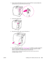
5.
Slide out the formatter board and set it on a clean, flat, grounded surface.
6.
Align the groove on the side of the flash memory card with the notches in the connector
and push it in the slot until it is fully seated.
CAUTION
Do not insert the flash memory card at an angle.
Note
The first flash memory slot marked "Firmware Slot" is reserved for firmware only. Slots 2 and
3 should be used for all other solutions.
7.
Align the formatter board in the tracks at the top and bottom of the slot, and then slide
the board back into the printer. Replace and tighten the eight screws removed in step 4.
246
Appendix A
Working with memory and print server cards
ENWW