HP 6125G HP 6125G & 6125G/XG Blade Switches Fundamentals Configuration - Page 111
Configuration procedure, from the TFTP server to the root directory of the master's storage media.
 |
View all HP 6125G manuals
Add to My Manuals
Save this manual to your list of manuals |
Page 111 highlights
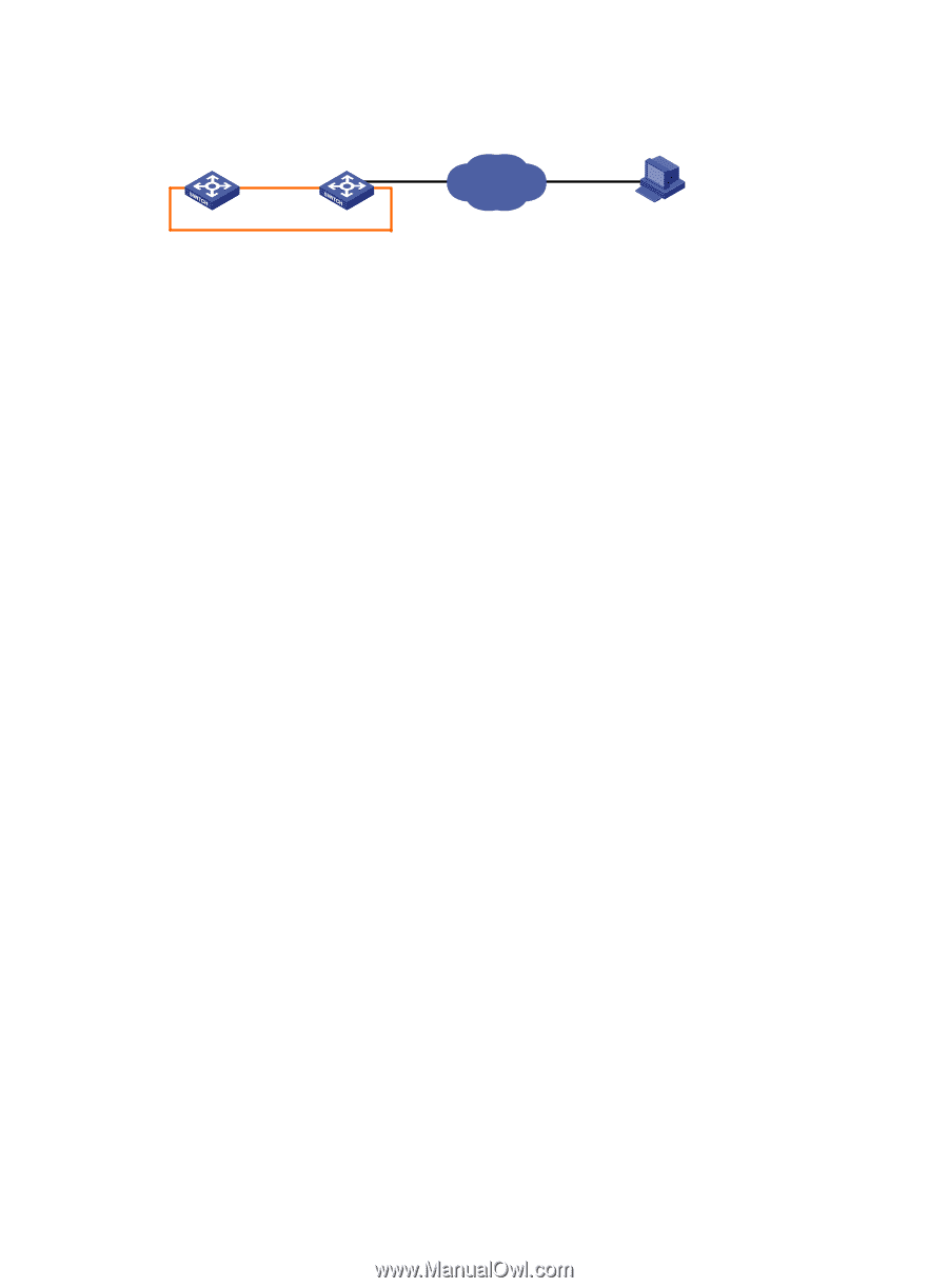
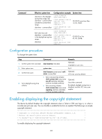
Figure 42 Network diagram Master (Member_ID=1) Subordinate (Member_ID=2) Internet 2.2.2.2/24 IRF 1.1.1.1/24 Note: The orange line represents the IRF link. TFTP server Configuration procedure 1. Configure the TFTP server: # Enable the TFTP server function. (Details not shown.) # Save the patch package file patch_package.bin to the working directory of TFTP server. (Details not shown.) 2. Configure the IRF fabric: # Use the save command to save the current system configuration. (Details not shown.) # Examine the space of the Flash on each switch. If the free space is not sufficient for the patches, delete unused files to release space. (Details not shown.) # Load patch_package.bin from the TFTP server to the root directory of the master's storage media. tftp 2.2.2.2 get patch_package.bin # Load patch_package.bin from the TFTP server to the root directory of the subordinate switch's storage media. tftp 2.2.2.2 get patch_package.bin slot2#flash:/patch_package.bin # Install the patch package file. system-view [IRF] patch install file patch_package.bin Patches will be installed. Continue? [Y/N]:y Do you want to continue running patches after reboot? [Y/N]:y Installing patches........ 3. Use the display patch information command to verify that the patches have been installed and running. (Details not shown.) 105
-
 1
1 -
2
-
3
-
4
-
5
-
6
-
7
-
8
-
9
-
10
-
11
-
12
-
13
-
14
-
15
-
16
-
17
-
18
-
19
-
20
-
21
-
22
-
23
-
24
-
25
-
26
-
27
-
28
-
29
-
30
-
31
-
32
-
33
-
34
-
35
-
36
-
37
-
38
-
39
-
40
-
41
-
42
-
43
-
44
-
45
-
46
-
47
-
48
-
49
-
50
-
51
-
52
-
53
-
54
-
55
-
56
-
57
-
58
-
59
-
60
-
61
-
62
-
63
-
64
-
65
-
66
-
67
-
68
-
69
-
70
-
71
-
72
-
73
-
74
-
75
-
76
-
77
-
78
-
79
-
80
-
81
-
82
-
83
-
84
-
85
-
86
-
87
-
88
-
89
-
90
-
91
-
92
-
93
-
94
-
95
-
96
-
97
-
98
-
99
-
100
-
101
-
102
-
103
-
104
-
105
-
 106
106 -
 107
107 -
 108
108 -
 109
109 -
 110
110 -
 111
111 -
 112
112 -
 113
113 -
 114
114 -
 115
115 -
 116
116 -
117
-
118
-
119
-
120
-
121
-
122
-
123
-
124
-
125
-
126
-
127
-
128
-
129
-
130
-
131
-
132
-
133
-
134
-
135
 |
 |