HP 6125G HP 6125G & 6125G/XG Blade Switches Fundamentals Configuration - Page 64
Configuration procedure, Network diagram
 |
View all HP 6125G manuals
Add to My Manuals
Save this manual to your list of manuals |
Page 64 highlights
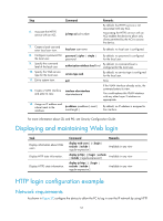
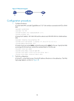
Figure 27 Network diagram Configuration procedure 1. Configure the device: # Create VLAN 999, and add GigabitEthernet 1/0/1 (the interface connected to the PC) to VLAN 999. system-view [Sysname] vlan 999 [Sysname-vlan999] port GigabitEthernet 1/0/1 [Sysname-vlan999] quit # Assign the IP address 192.168.0.58 and the subnet mask 255.255.255.0 to VLAN-interface 999. [Sysname] interface vlan-interface 999 [Sysname-VLAN-interface999] ip address 192.168.0.58 255.255.255.0 [Sysname-VLAN-interface999] quit # Create a local user named admin, and set the password to admin for the user. Specify the Web service type for the local user, and set the command level to 3 for this user. [Sysname] local-user admin [Sysname-luser-admin] service-type web [Sysname-luser-admin] authorization-attribute level 3 [Sysname-luser-admin] password simple admin 2. Verify the configuration: # On the PC, run the Web browser. Enter the IP address of the device in the address bar. The Web login page appears, as shown in Figure 28. 58
-
 1
1 -
2
-
3
-
4
-
5
-
6
-
7
-
8
-
9
-
10
-
11
-
12
-
13
-
14
-
15
-
16
-
17
-
18
-
19
-
20
-
21
-
22
-
23
-
24
-
25
-
26
-
27
-
28
-
29
-
30
-
31
-
32
-
33
-
34
-
35
-
36
-
37
-
38
-
39
-
40
-
41
-
42
-
43
-
44
-
45
-
46
-
47
-
48
-
49
-
50
-
51
-
52
-
53
-
54
-
55
-
56
-
57
-
58
-
 59
59 -
 60
60 -
 61
61 -
 62
62 -
 63
63 -
 64
64 -
 65
65 -
 66
66 -
 67
67 -
 68
68 -
 69
69 -
70
-
71
-
72
-
73
-
74
-
75
-
76
-
77
-
78
-
79
-
80
-
81
-
82
-
83
-
84
-
85
-
86
-
87
-
88
-
89
-
90
-
91
-
92
-
93
-
94
-
95
-
96
-
97
-
98
-
99
-
100
-
101
-
102
-
103
-
104
-
105
-
106
-
107
-
108
-
109
-
110
-
111
-
112
-
113
-
114
-
115
-
116
-
117
-
118
-
119
-
120
-
121
-
122
-
123
-
124
-
125
-
126
-
127
-
128
-
129
-
130
-
131
-
132
-
133
-
134
-
135
 |
 |