HP 6125G HP 6125G & 6125G/XG Blade Switches Fundamentals Configuration - Page 50
Setting up the configuration environment, Authentication, Configuration task, Reference, AT&F
 |
View all HP 6125G manuals
Add to My Manuals
Save this manual to your list of manuals |
Page 50 highlights
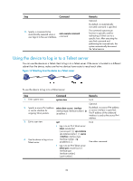
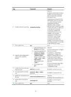
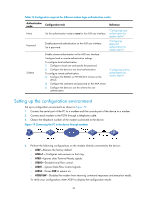
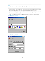
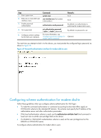
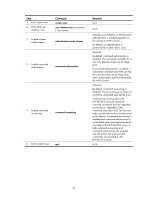
Table 16 Configuration required for different modem login authentication modes Authentication mode None Password Scheme Configuration task Set the authentication mode to none for the AUX user interface. Enable password authentication on the AUX user interface. Set a password. Enable scheme authentication on the AUX user interface. Configure local or remote authentication settings. To configure local authentication: 1. Configure a local user and specify the password. 2. Configure the device to use local authentication. To configure remote authentication: 3. Configure the RADIUS or HWTACACS scheme on the device. 4. Configure the username and password on the AAA server. 5. Configure the device to use the scheme for user authentication. Reference "Configuring none authentication for modem dial-in" "Configuring password authentication for modem dial-in" "Configuring scheme authentication for modem dial-in" Setting up the configuration environment Set up a configuration environment as shown in Figure 19: 1. Connect the serial port of the PC to a modem and the console port of the device to a modem. 2. Connect each modem to the PSTN through a telephone cable. 3. Obtain the telephone number of the modem connected to the device. Figure 19 Connecting the PC to the device through modems 4. Perform the following configurations on the modem directly connected to the device: { AT&F-Restores the factory default. { ATS0=1-Configures auto-answer on first ring. { AT&D-Ignores data Terminal Ready signals. { AT&K0-Disables local flow control. { AT&R1-Ignores Data Flow Control signals. { AT&S0-Forces DSR to remain on. { ATEQ1&W-Disables the modem from returning command responses and execution results. To verify your configuration, enter AT&V to display the configuration results. 44
-
 1
1 -
2
-
3
-
4
-
5
-
6
-
7
-
8
-
9
-
10
-
11
-
12
-
13
-
14
-
15
-
16
-
17
-
18
-
19
-
20
-
21
-
22
-
23
-
24
-
25
-
26
-
27
-
28
-
29
-
30
-
31
-
32
-
33
-
34
-
35
-
36
-
37
-
38
-
39
-
40
-
41
-
42
-
43
-
44
-
 45
45 -
 46
46 -
 47
47 -
 48
48 -
 49
49 -
 50
50 -
 51
51 -
 52
52 -
 53
53 -
 54
54 -
 55
55 -
56
-
57
-
58
-
59
-
60
-
61
-
62
-
63
-
64
-
65
-
66
-
67
-
68
-
69
-
70
-
71
-
72
-
73
-
74
-
75
-
76
-
77
-
78
-
79
-
80
-
81
-
82
-
83
-
84
-
85
-
86
-
87
-
88
-
89
-
90
-
91
-
92
-
93
-
94
-
95
-
96
-
97
-
98
-
99
-
100
-
101
-
102
-
103
-
104
-
105
-
106
-
107
-
108
-
109
-
110
-
111
-
112
-
113
-
114
-
115
-
116
-
117
-
118
-
119
-
120
-
121
-
122
-
123
-
124
-
125
-
126
-
127
-
128
-
129
-
130
-
131
-
132
-
133
-
134
-
135
 |
 |
