HP Superdome SX2000 User Service Guide, Seventh Edition - HP Integrity Superdo - Page 10

I/O Expansion Cabinet Power Requirements Without SMS, I/O Expansion Cabinet ac Power Cords

Page 10 highlights

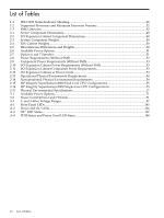
List of Tables 1-1 HSO LED Status Indicator Meaning 28 1-2 Supported Processors and Minimum Firmware Versions 32 1-3 SMS Lifecycles...42 2-1 Server Component Dimensions...49 2-2 I/O Expansion Cabinet Component Dimensions 49 2-3 System Component Weights...49 2-4 IOX Cabinet Weights...50 2-5 Miscellaneous Dimensions and Weights 50 2-6 Available Power Options...51 2-7 Option 6 and 7 Specifics...51 2-8 Power Requirements (Without SMS 52 2-9 Component Power Requirements (Without SMS 53 2-10 I/O Expansion Cabinet Power Requirements (Without SMS 53 2-11 I/O Expansion Cabinet Component Power Requirements 53 2-12 I/O Expansion Cabinet ac Power Cords 54 2-13 Operational Physical Environment Requirements 54 2-14 Nonoperational Physical Environment Requirements 54 2-15 HP Integrity Superdome/sx2000 Dual-Core CPU Configurations 55 2-16 HP Integrity Superdome/sx2000 Single-Core CPU Configurations 55 2-17 Physical Environmental Specifications 57 3-1 Available Power Options...71 3-2 Power Cord Option 6 and 7 Details 71 3-3 4- and 5-Wire Voltage Ranges...87 A-1 Front Panel LEDs...145 A-2 Power and OL* LEDs...146 A-3 OL* LED States...147 A-4 PDH Status and Power Good LED States 148 10 List of Tables

  • 1
  • 2
  • 3
  • 4
  • 5
  • 6
  • 7
  • 8
  • 9
  • 10
  • 11
  • 12
  • 13
  • 14
  • 15
  • 16
  • 17
  • 18
  • 19
  • 20
  • 21
  • 22
  • 23
  • 24
  • 25
  • 26
  • 27
  • 28
  • 29
  • 30
  • 31
  • 32
  • 33
  • 34
  • 35
  • 36
  • 37
  • 38
  • 39
  • 40
  • 41
  • 42
  • 43
  • 44
  • 45
  • 46
  • 47
  • 48
  • 49
  • 50
  • 51
  • 52
  • 53
  • 54
  • 55
  • 56
  • 57
  • 58
  • 59
  • 60
  • 61
  • 62
  • 63
  • 64
  • 65
  • 66
  • 67
  • 68
  • 69
  • 70
  • 71
  • 72
  • 73
  • 74
  • 75
  • 76
  • 77
  • 78
  • 79
  • 80
  • 81
  • 82
  • 83
  • 84
  • 85
  • 86
  • 87
  • 88
  • 89
  • 90
  • 91
  • 92
  • 93
  • 94
  • 95
  • 96
  • 97
  • 98
  • 99
  • 100
  • 101
  • 102
  • 103
  • 104
  • 105
  • 106
  • 107
  • 108
  • 109
  • 110
  • 111
  • 112
  • 113
  • 114
  • 115
  • 116
  • 117
  • 118
  • 119
  • 120
  • 121
  • 122
  • 123
  • 124
  • 125
  • 126
  • 127
  • 128
  • 129
  • 130
  • 131
  • 132
  • 133
  • 134
  • 135
  • 136
  • 137
  • 138
  • 139
  • 140
  • 141
  • 142
  • 143
  • 144
  • 145
  • 146
  • 147
  • 148
  • 149
  • 150
  • 151
  • 152
  • 153
  • 154
  • 155
  • 156
  • 157
  • 158
  • 159
  • 160
  • 161
  • 162
  • 163
  • 164
  • 165
  • 166
  • 167
  • 168
  • 169
  • 170
  • 171
  • 172
  • 173
  • 174
  • 175
  • 176
  • 177
  • 178
  • 179
  • 180
  • 181
  • 182
  • 183
  • 184
  • 185
  • 186
  • 187
  • 188
  • 189
  • 190
  • 191
  • 192
  • 193
  • 194
  • 195
  • 196
  • 197
  • 198
  • 199
  • 200

List of Tables
1-1
HSO LED Status Indicator Meaning
.............................................................................................
28
1-2
Supported Processors and Minimum Firmware Versions
............................................................
32
1-3
SMS Lifecycles
...............................................................................................................................
42
2-1
Server Component Dimensions
....................................................................................................
49
2-2
I/O Expansion Cabinet Component Dimensions
..........................................................................
49
2-3
System Component Weights
.........................................................................................................
49
2-4
IOX Cabinet Weights
.....................................................................................................................
50
2-5
Miscellaneous Dimensions and Weights
.......................................................................................
50
2-6
Available Power Options
...............................................................................................................
51
2-7
Option 6 and 7 Specifics
................................................................................................................
51
2-8
Power Requirements (Without SMS)
............................................................................................
52
2-9
Component Power Requirements (Without SMS)
........................................................................
53
2-10
I/O Expansion Cabinet Power Requirements (Without SMS)
.......................................................
53
2-11
I/O Expansion Cabinet Component Power Requirements
............................................................
53
2-12
I/O Expansion Cabinet ac Power Cords
........................................................................................
54
2-13
Operational Physical Environment Requirements
........................................................................
54
2-14
Nonoperational Physical Environment Requirements
.................................................................
54
2-15
HP Integrity Superdome/sx2000 Dual-Core CPU Configurations
...............................................
55
2-16
HP Integrity Superdome/sx2000 Single-Core CPU Configurations
.............................................
55
2-17
Physical Environmental Specifications
.........................................................................................
57
3-1
Available Power Options
...............................................................................................................
71
3-2
Power Cord Option 6 and 7 Details
...............................................................................................
71
3-3
4- and 5-Wire Voltage Ranges
.......................................................................................................
87
A-1
Front Panel LEDs
.........................................................................................................................
145
A-2
Power and OL* LEDs
...................................................................................................................
146
A-3
OL* LED States
............................................................................................................................
147
A-4
PDH Status and Power Good LED States
....................................................................................
148
10
List of Tables