HP Superdome SX2000 User Service Guide, Seventh Edition - HP Integrity Superdo - Page 199
Support Management Station, Msee Nsee Psee Rsee Ssee
 |
View all HP Superdome SX2000 manuals
Add to My Manuals
Save this manual to your list of manuals |
Page 199 highlights
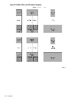
LPM, 19 M m-Link cable description, 42 MAC address, 100 management processor, (see MP) moving the system, 72 MP detailed description, 24 displaying the customer LAN parameters, 100 exiting the main menu, 101 general description, 22 invoking a partition console, 104 invoking the virtual front panel, 103 physical connection to the customer LAN, 98 returning to the main menu, 101 setting the customer LAN parameters, 100 shown in system, 24 viewing the virtual front panel screen, 103 N noise emission specifications, 56 nPartition access errors, 48 P packing carton contents, 60 PDCA, 19 4-wire voltage verification, 84 5-wire voltage verification, 84 ac breaker power on sequence, 179 ac breakers, 96 installation, 86 redundancy provision, 20 unpacking, 71 wiring configurations, 71, 86 plenum rated data cables, 20 PM UGUY location, 22 PM3 BPS sensor monitor, 21 functions performed, 23 inlet air sensor monitor, 21 post installation check, 112 power DP rated power cables, 20 housekeeping, 96 turning on housekeeping, 178 power dissipation, 54-55 power distribution component assembly, (see PDCA) power monitor 3, (see PM3) power on sequence, 21 power options option 6, 51-52 option 7, 51, 52 power requirements I/O expansion cabinet, 53 system, 52 power supply mounting screws, 66 power up 48 V dc enablement, 21 5.3 V dc enablement, 21 power on sequence for cabinets, 104 processors dual-die, 19 ItaniumTM, 17 mixing rules, 48 PA-RISC, 17 R ramp extensions, 65 RCS detailed description, 28 location on backplane, 29 part of clock subsystem, 27 redundant clock source module, (see RCS) repackaging checklist, 71 returning equipment, 71 routing I/O cables, 91 S SBCH board revision information, 23 part of MP, 24 POST start, 21 shown in system, 24 USB hub provisioning, 22 server errors global shared memory, 48 hardware correctable, 48 nPartition access, 48 shipping dimensions and weights, 50 signoff, customer, 112 single board computer hub, (see SBCH) site of installation, 72 site preparation verification, 60 skins, attaching, 75 space requirements computer room layout, 185 equipment footprint templates, 185 subnet mask, 100 Superdome system air flow, 56 computer room layout, 185 history, 17 I/O expansion cabinet, 18 left cabinet, 18 right cabinet, 18 three cabinet configurations, 18 Support Management Station private LAN IP address, 99 private LAN port designations, 100 switch fabric general description, 27 system backplane 48 V supply pinouts, 29 description of power supply modules, 30 functionality provided, 26 199
-
 1
1 -
2
-
3
-
4
-
5
-
6
-
7
-
8
-
9
-
10
-
11
-
12
-
13
-
14
-
15
-
16
-
17
-
18
-
19
-
20
-
21
-
22
-
23
-
24
-
25
-
26
-
27
-
28
-
29
-
30
-
31
-
32
-
33
-
34
-
35
-
36
-
37
-
38
-
39
-
40
-
41
-
42
-
43
-
44
-
45
-
46
-
47
-
48
-
49
-
50
-
51
-
52
-
53
-
54
-
55
-
56
-
57
-
58
-
59
-
60
-
61
-
62
-
63
-
64
-
65
-
66
-
67
-
68
-
69
-
70
-
71
-
72
-
73
-
74
-
75
-
76
-
77
-
78
-
79
-
80
-
81
-
82
-
83
-
84
-
85
-
86
-
87
-
88
-
89
-
90
-
91
-
92
-
93
-
94
-
95
-
96
-
97
-
98
-
99
-
100
-
101
-
102
-
103
-
104
-
105
-
106
-
107
-
108
-
109
-
110
-
111
-
112
-
113
-
114
-
115
-
116
-
117
-
118
-
119
-
120
-
121
-
122
-
123
-
124
-
125
-
126
-
127
-
128
-
129
-
130
-
131
-
132
-
133
-
134
-
135
-
136
-
137
-
138
-
139
-
140
-
141
-
142
-
143
-
144
-
145
-
146
-
147
-
148
-
149
-
150
-
151
-
152
-
153
-
154
-
155
-
156
-
157
-
158
-
159
-
160
-
161
-
162
-
163
-
164
-
165
-
166
-
167
-
168
-
169
-
170
-
171
-
172
-
173
-
174
-
175
-
176
-
177
-
178
-
179
-
180
-
181
-
182
-
183
-
184
-
185
-
186
-
187
-
188
-
189
-
190
-
191
-
192
-
193
-
 194
194 -
 195
195 -
 196
196 -
 197
197 -
 198
198 -
 199
199 -
 200
200
 |
 |