HP Superdome SX2000 User Service Guide, Seventh Edition - HP Integrity Superdo - Page 28
Hot-Swap Oscillator, sx2000 RCS Module, Table 1-1 HSO LED Status Indicator Meaning
 |
View all HP Superdome SX2000 manuals
Add to My Manuals
Save this manual to your list of manuals |
Page 28 highlights
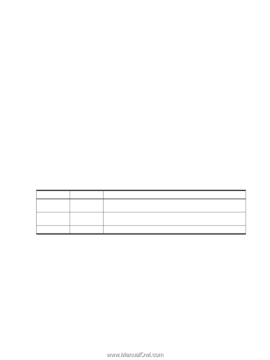
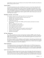
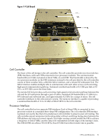
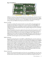
if it is providing a signal of the correct amplitude to the cell boards and XBCs. Its output is also an alarm signal to the RPM FPGA. System clocks can originate from these input sources: • the single-ended external clock input MCX connector • the 280 MHz margin oscillator on the redundant clock source (RCS) board • one of the 266.667 MHz oscillators on one of the HSO modules The source selection is determined either by firmware or by logic in the RCS. The clock source has alarm signals to indicate the following health status conditions to the cabinet management subsystem: • Loss of power and loss of clock for each of the clock oscillator boards • Loss of clock output to the backplanes The sx2000 clock system differs from the sx1000 clock system in that the system clocks are only supplied to the backplane crossbar ASICs and the cell boards. System clocks are not distributed to the I/O backplanes. Instead, independent local clock distribution is provided on the I/O backplane. Hot-Swap Oscillator Two hot-swappable clock oscillators combine the outputs of both oscillators to form an N+1 redundant fault tolerant clock source. The resultant clock source drives clocks over connector and cable interfaces to the system backplanes. The HSO board contains a 266.667 MHz PECL oscillator. The output from this oscillator drives a 266.667 MHz band-pass SAW filter that drives a monolithic IC power amplifier. The output of the power amplifier is a 266.667 sine wave clock that goes to the RCS. The module also has two LEDs, one green and one yellow, that are visible through the module handle.Table 1-1 describes the HSO LEDs. The electrical signal that controls the LEDs is driven by the RCS. Table 1-1 HSO LED Status Indicator Meaning Green LED On Off Off Yellow LED Off On Off Meaning Module OK. HSO is producing a clock of the correct amplitude and frequency and is plugged into its connector. Module needs attention. HSO is not producing a clock of the correct amplitude or frequency, but it is plugged into its connector. Module power is off. sx2000 RCS Module The sx2000 RCS module supplies clocks to the Superdome sx2000 backplane, communicates clock alarms to the RPM, and accepts control input from the RPM. It has an I2C EEPROM on the module so that the firmware can inventory the module on system power on. The RCS supplies 16 copies of the sine wave system clock to the sx2000 system backplane. Eight copies go to the eight cell boards, six copies go to the six XBCs on the system backplane, and two copies to the backplane clock power detector. In normal operation, the RCS selects one of the two HSOs as the source of clocks for the platform. The HSO selected depends on whether the HSO is plugged into the backplane and on whether it has a valid output level. This selection is overridden if there is a connection from the clock input MCX connector on the master backplane. Figure 1-6 shows the locations of the HSOs and RCS on the backplane. 28 Overview
-
 1
1 -
2
-
3
-
4
-
5
-
6
-
7
-
8
-
9
-
10
-
11
-
12
-
13
-
14
-
15
-
16
-
17
-
18
-
19
-
20
-
21
-
22
-
 23
23 -
 24
24 -
 25
25 -
 26
26 -
 27
27 -
 28
28 -
 29
29 -
 30
30 -
 31
31 -
 32
32 -
 33
33 -
34
-
35
-
36
-
37
-
38
-
39
-
40
-
41
-
42
-
43
-
44
-
45
-
46
-
47
-
48
-
49
-
50
-
51
-
52
-
53
-
54
-
55
-
56
-
57
-
58
-
59
-
60
-
61
-
62
-
63
-
64
-
65
-
66
-
67
-
68
-
69
-
70
-
71
-
72
-
73
-
74
-
75
-
76
-
77
-
78
-
79
-
80
-
81
-
82
-
83
-
84
-
85
-
86
-
87
-
88
-
89
-
90
-
91
-
92
-
93
-
94
-
95
-
96
-
97
-
98
-
99
-
100
-
101
-
102
-
103
-
104
-
105
-
106
-
107
-
108
-
109
-
110
-
111
-
112
-
113
-
114
-
115
-
116
-
117
-
118
-
119
-
120
-
121
-
122
-
123
-
124
-
125
-
126
-
127
-
128
-
129
-
130
-
131
-
132
-
133
-
134
-
135
-
136
-
137
-
138
-
139
-
140
-
141
-
142
-
143
-
144
-
145
-
146
-
147
-
148
-
149
-
150
-
151
-
152
-
153
-
154
-
155
-
156
-
157
-
158
-
159
-
160
-
161
-
162
-
163
-
164
-
165
-
166
-
167
-
168
-
169
-
170
-
171
-
172
-
173
-
174
-
175
-
176
-
177
-
178
-
179
-
180
-
181
-
182
-
183
-
184
-
185
-
186
-
187
-
188
-
189
-
190
-
191
-
192
-
193
-
194
-
195
-
196
-
197
-
198
-
199
-
200
 |
 |