HP Superdome SX2000 User Service Guide, Seventh Edition - HP Integrity Superdo - Page 29
Cabinet ID, Cell ID, Backplane Power Requirements and Power Distribution
 |
View all HP Superdome SX2000 manuals
Add to My Manuals
Save this manual to your list of manuals |
Page 29 highlights
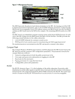
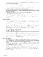
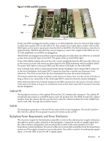
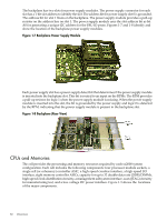
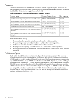
Figure 1-6 HSO and RCS Locations If only one HSO is plugged in and its output is of valid amplitude, then it is selected. If its output is valid, then a green LED on the HSO is lit. If its output is not valid, then a yellow LED on the HSO lights and an alarm signal goes from the RCS to the RPM. The RCS provides a clock that is approximately 100 KHz less than the correct frequency, even if the output of the HSOs are not of valid amplitude or no HSOs are plugged in. If both HSOs are plugged in and their output amplitudes are valid, then one of the two is selected as the clock source by logic on the RCS. The green LEDs on both HSOs light. If one of the HSOs outputs does not have the correct amplitude then the RCS uses the other one as the source of clocks and sends an alarm signal to the RPM indicating which oscillator failed. The green LED lights on the good HSO and the yellow LED lights on the failed HSO. If an external clock cable is connected from the master backplane clock output MCX connector to the slave backplane clock input MCX connector, then this overrides any firmware clock selections. The clock source from the slave backplane becomes the master backplane. If firmware selects the margin oscillator as the source of clocks, then it is the source of clocks as long as there is no connection to the clock input MCX connector from the master backplane. If the firmware selects the external margin clock SMB connectors as the source of clocks, then it is the source of clocks as long as no connection exists to the clock input MCX connector from the master backplane. Cabinet ID The backplane receives a 6-bit cabinet ID from the CLU interface J64 connector. The cabinet ID is buffered and routed to each RPM and to each cell module slot. The RPM decodes the cabinet number from the cabinet ID and uses this bit to alter the cabinet number bit in the ALBID byte sent to each XBC through the serial bit stream. Cell ID The backplane generates a 3-bit slot ID for each cell slot in the backplane. The slot ID and five bits from the cabinet ID are passed to each cell module as the cell ID. Backplane Power Requirements and Power Distribution The dc power supply for the backplane assembly runs from the cabinet power supply subsystem through two power cables attached to the backplane. Connectors for the dc supply input have the same reference designators and are physically located in the same position as on the Superdome system backplane. The power cables are reused cable assemblies from the Superdome system and the supply connection is not redundant. One cable is used for housekeeping supply input. A second cable is used for 48 V supply input. Backplane 29
-
 1
1 -
2
-
3
-
4
-
5
-
6
-
7
-
8
-
9
-
10
-
11
-
12
-
13
-
14
-
15
-
16
-
17
-
18
-
19
-
20
-
21
-
22
-
23
-
 24
24 -
 25
25 -
 26
26 -
 27
27 -
 28
28 -
 29
29 -
 30
30 -
 31
31 -
 32
32 -
 33
33 -
 34
34 -
35
-
36
-
37
-
38
-
39
-
40
-
41
-
42
-
43
-
44
-
45
-
46
-
47
-
48
-
49
-
50
-
51
-
52
-
53
-
54
-
55
-
56
-
57
-
58
-
59
-
60
-
61
-
62
-
63
-
64
-
65
-
66
-
67
-
68
-
69
-
70
-
71
-
72
-
73
-
74
-
75
-
76
-
77
-
78
-
79
-
80
-
81
-
82
-
83
-
84
-
85
-
86
-
87
-
88
-
89
-
90
-
91
-
92
-
93
-
94
-
95
-
96
-
97
-
98
-
99
-
100
-
101
-
102
-
103
-
104
-
105
-
106
-
107
-
108
-
109
-
110
-
111
-
112
-
113
-
114
-
115
-
116
-
117
-
118
-
119
-
120
-
121
-
122
-
123
-
124
-
125
-
126
-
127
-
128
-
129
-
130
-
131
-
132
-
133
-
134
-
135
-
136
-
137
-
138
-
139
-
140
-
141
-
142
-
143
-
144
-
145
-
146
-
147
-
148
-
149
-
150
-
151
-
152
-
153
-
154
-
155
-
156
-
157
-
158
-
159
-
160
-
161
-
162
-
163
-
164
-
165
-
166
-
167
-
168
-
169
-
170
-
171
-
172
-
173
-
174
-
175
-
176
-
177
-
178
-
179
-
180
-
181
-
182
-
183
-
184
-
185
-
186
-
187
-
188
-
189
-
190
-
191
-
192
-
193
-
194
-
195
-
196
-
197
-
198
-
199
-
200
 |
 |
