HP Superdome SX2000 User Service Guide, Seventh Edition - HP Integrity Superdo - Page 84
Installing and Verifying the PDCA, further investigation.
 |
View all HP Superdome SX2000 manuals
Add to My Manuals
Save this manual to your list of manuals |
Page 84 highlights
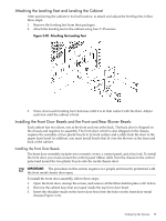
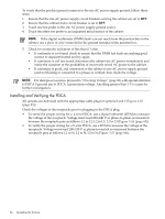
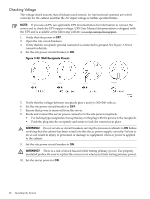
To verify that the product ground connects to the site AC power supply ground, follow these steps: 1. Ensure that the site AC power supply circuit breakers serving the cabinet are set to OFF. 2. Ensure that the cabinet main circuit breaker is set to OFF. 3. Touch one test probe to the site AC power supply ground source. 4. Touch the other test probe to an unpainted metal surface of the cabinet. NOTE: If the digital multimeter (DMM) leads can not reach from the junction box to the cabinet, use a piece of wire connected to the ground terminal of the junction box. 5. Check for continuity indication of less than 0.1 ohm. • If continuity is not found, check to ensure that the DMM test leads are making good contact to unpainted metal and try again. • If continuity is still not found, disconnect the cabinet site AC power immediately and notify the customer of the probability of incorrectly wired AC power to the cabinet. • If continuity is good, and connection of the cabinet to site AC power supply ground (and not floating or connected to a phase) is verified, then check the voltage. NOTE: For dual power sources, proceed to "Checking Voltage" (page 88) with special attention to PDCA 0 ground pin to PDCA 1 ground pin voltage. Anything greater than 3 V is cause for further investigation. Installing and Verifying the PDCA All systems are delivered with the appropriate cable plug for options 6 and 7 (Figure 3-25 (page 85)). Check the voltages at the receptacle prior to plugging in the PDCA plug. • To verify the proper wiring for a 4-wire PDCA, use a digital voltmeter (DVM) to measure the voltage at the receptacle. Voltage must read 200-240 V ac phase-to-phase as measured between the receptacle pins as follows: L1 to L2, L2 to L3, L1 to L3 (Figure 3-26 (page 85)). • To verify the proper wiring for a 5-wire PDCA, use a DVM to measure the voltage at the receptacle. Voltage must read 200-240 V ac phase-to-neutral as measured between the receptacle pins as follows: L1 to N, L2 to N, L3 to N (Figure 3-27 (page 86)). 84 Installing the System
-
 1
1 -
2
-
3
-
4
-
5
-
6
-
7
-
8
-
9
-
10
-
11
-
12
-
13
-
14
-
15
-
16
-
17
-
18
-
19
-
20
-
21
-
22
-
23
-
24
-
25
-
26
-
27
-
28
-
29
-
30
-
31
-
32
-
33
-
34
-
35
-
36
-
37
-
38
-
39
-
40
-
41
-
42
-
43
-
44
-
45
-
46
-
47
-
48
-
49
-
50
-
51
-
52
-
53
-
54
-
55
-
56
-
57
-
58
-
59
-
60
-
61
-
62
-
63
-
64
-
65
-
66
-
67
-
68
-
69
-
70
-
71
-
72
-
73
-
74
-
75
-
76
-
77
-
78
-
 79
79 -
 80
80 -
 81
81 -
 82
82 -
 83
83 -
 84
84 -
 85
85 -
 86
86 -
 87
87 -
 88
88 -
 89
89 -
90
-
91
-
92
-
93
-
94
-
95
-
96
-
97
-
98
-
99
-
100
-
101
-
102
-
103
-
104
-
105
-
106
-
107
-
108
-
109
-
110
-
111
-
112
-
113
-
114
-
115
-
116
-
117
-
118
-
119
-
120
-
121
-
122
-
123
-
124
-
125
-
126
-
127
-
128
-
129
-
130
-
131
-
132
-
133
-
134
-
135
-
136
-
137
-
138
-
139
-
140
-
141
-
142
-
143
-
144
-
145
-
146
-
147
-
148
-
149
-
150
-
151
-
152
-
153
-
154
-
155
-
156
-
157
-
158
-
159
-
160
-
161
-
162
-
163
-
164
-
165
-
166
-
167
-
168
-
169
-
170
-
171
-
172
-
173
-
174
-
175
-
176
-
177
-
178
-
179
-
180
-
181
-
182
-
183
-
184
-
185
-
186
-
187
-
188
-
189
-
190
-
191
-
192
-
193
-
194
-
195
-
196
-
197
-
198
-
199
-
200
 |
 |