HP Superdome SX2000 User Service Guide, Seventh Edition - HP Integrity Superdo - Page 27
Switch Fabrics, Backplane Monitor and Control, I2C Bus Distribution, Clock Subsystem
 |
View all HP Superdome SX2000 manuals
Add to My Manuals
Save this manual to your list of manuals |
Page 27 highlights
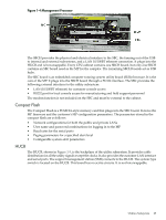
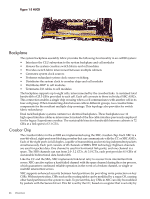
a hard cell reset, which causes secure firmware to be entered. This bit is cleared by secure firmware before passing control to an OS. Switch Fabrics The system backplane houses the switch fabric that connects to each of the cell modules. The crossbar switch is implemented by a three-link-per-cell topology: three independent switch fabrics connected in parallel. This topology provides switch fabric redundancy in the crossbar switch. The backplane crossbar can be extended to an additional crossbar in a second backplane for a dual backplane configuration. It connects through a high-speed cable interface to the second backplane. This 12-cable high-speed interface replaces the flex cable interface previously used on the Superdome system. Backplane Monitor and Control The backplane implements the following monitor and control functions:. • Backplane detect and enable functions to and from the CLU • Backplane LED controls from the CLU • Backplane JTAG distribution and chains • Cabinet ID from the CLU • Reset and power manager FPGA (RPM) and JTAG interface and header for external programming • XBC reset, configuration and control • IIC bus distribution to and from the CLU • Clock subsystem monitor and control • Power supply monitor and control • Cell detect, power monitor, reset and enable to and from the CLU • JTAG and USB data distribution to and from each cell module • Cell ID to each cell module • OSP FPGA functionality I2C Bus Distribution The sx2000 system I2C bus extends to the Superdome backplane (SDBP) assembly through a cable connected from the CLU subsystem. This cable connects from J17 on the CLU to J64 on the SDBP. The clock and data signals on this cable are buffered through I2C bus extenders on the CLU and on the backplane. The I2C bus is routed to an I2C multiplexer on the backplane where the bus is isolated into four bus segments. Three bus segments are dedicated to connections to the three RPMs. The remaining segment is used to daisy-chain the remaining addressable devices on the bus. Each bus segment is addressed through a port on the I2C multiplexer. Clock Subsystem The backplane houses two hot-swap oscillator (HSO) modules. Each HSO board generates a system clock that feeds into the backplane. Each HSO output is routed to the redundant clock source (RCS) module. The RCS module accepts input from the two HSO modules and produces a single system clock, which is distributed on the backplane to all cell modules and XBC ASICs. System Clock Distribution The system components that receive the system clock are the eight cell boards that plug into to the backplane and the six XBC on the system backplane. Two backplane clock power detectors (one for each 8-way sine clock power splitter) are on the RCS. The backplane power detector sits at the end of the clock tree and measures the amplitude of the clock from the RCS to determine Backplane 27
-
 1
1 -
2
-
3
-
4
-
5
-
6
-
7
-
8
-
9
-
10
-
11
-
12
-
13
-
14
-
15
-
16
-
17
-
18
-
19
-
20
-
21
-
 22
22 -
 23
23 -
 24
24 -
 25
25 -
 26
26 -
 27
27 -
 28
28 -
 29
29 -
 30
30 -
 31
31 -
 32
32 -
33
-
34
-
35
-
36
-
37
-
38
-
39
-
40
-
41
-
42
-
43
-
44
-
45
-
46
-
47
-
48
-
49
-
50
-
51
-
52
-
53
-
54
-
55
-
56
-
57
-
58
-
59
-
60
-
61
-
62
-
63
-
64
-
65
-
66
-
67
-
68
-
69
-
70
-
71
-
72
-
73
-
74
-
75
-
76
-
77
-
78
-
79
-
80
-
81
-
82
-
83
-
84
-
85
-
86
-
87
-
88
-
89
-
90
-
91
-
92
-
93
-
94
-
95
-
96
-
97
-
98
-
99
-
100
-
101
-
102
-
103
-
104
-
105
-
106
-
107
-
108
-
109
-
110
-
111
-
112
-
113
-
114
-
115
-
116
-
117
-
118
-
119
-
120
-
121
-
122
-
123
-
124
-
125
-
126
-
127
-
128
-
129
-
130
-
131
-
132
-
133
-
134
-
135
-
136
-
137
-
138
-
139
-
140
-
141
-
142
-
143
-
144
-
145
-
146
-
147
-
148
-
149
-
150
-
151
-
152
-
153
-
154
-
155
-
156
-
157
-
158
-
159
-
160
-
161
-
162
-
163
-
164
-
165
-
166
-
167
-
168
-
169
-
170
-
171
-
172
-
173
-
174
-
175
-
176
-
177
-
178
-
179
-
180
-
181
-
182
-
183
-
184
-
185
-
186
-
187
-
188
-
189
-
190
-
191
-
192
-
193
-
194
-
195
-
196
-
197
-
198
-
199
-
200
 |
 |