HP Superdome SX2000 User Service Guide, Seventh Edition - HP Integrity Superdo - Page 185
Equipment Footprint Templates, Computer Room Layout Plan, D-3 SD64 Space Requirements
 |
View all HP Superdome SX2000 manuals
Add to My Manuals
Save this manual to your list of manuals |
Page 185 highlights
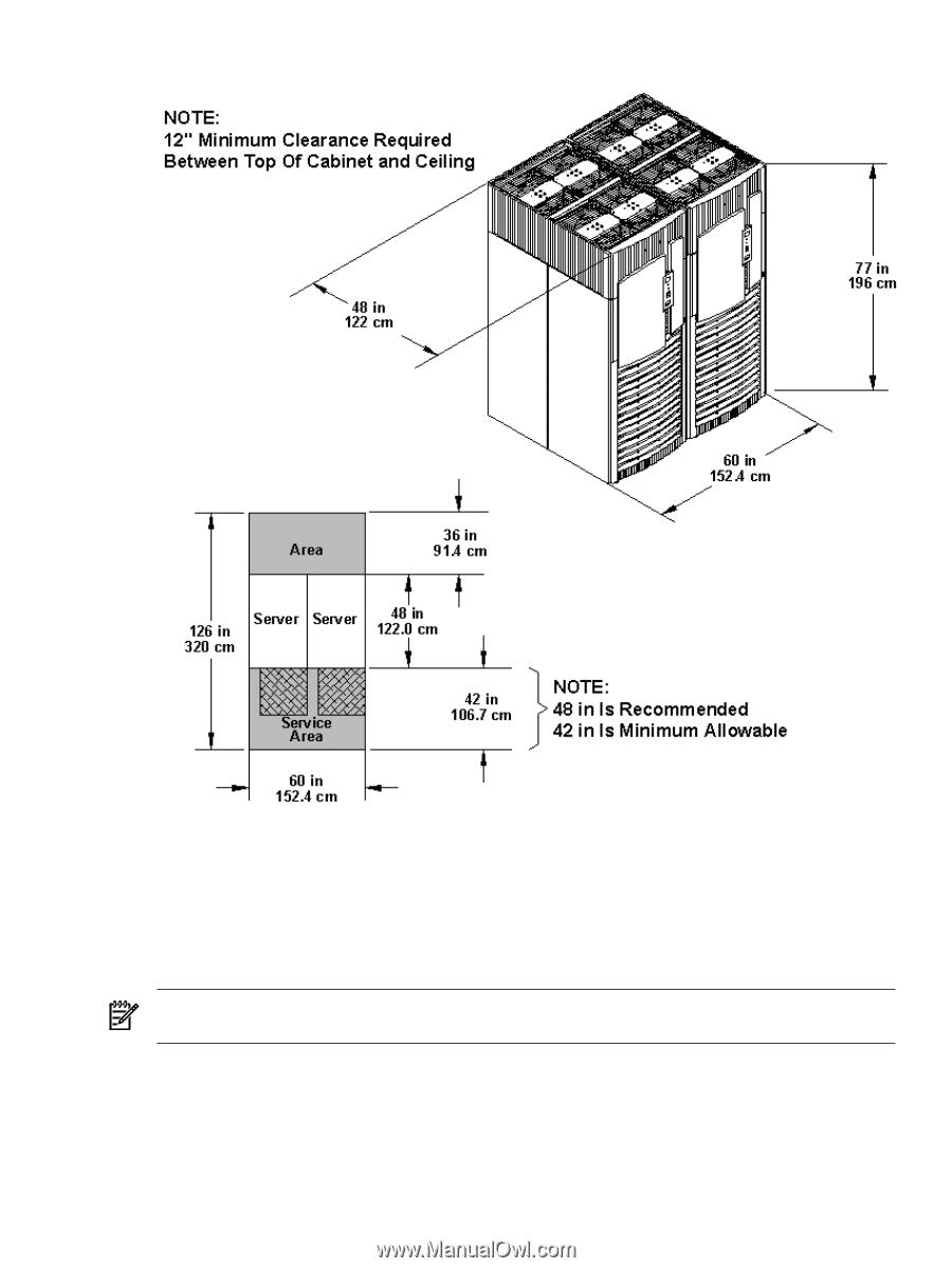
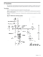
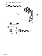
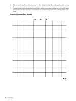
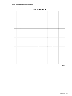
Figure D-3 SD64 Space Requirements Equipment Footprint Templates Equipment footprint templates are drawn to the same scale as the floor plan grid (1/4 inch = 1 foot). These templates show basic equipment dimensions and space requirements for servicing. The service areas shown on the template drawings are lightly shaded. Use equipment templates with the floor plan grid to define the location of the equipment to be installed in the computer room. NOTE: Photocopying typically changes the scale of copied drawings. If any templates are copied, then all templates and floor plan grids must also be copied. Computer Room Layout Plan To create a computer room layout, follow these steps: 1. Remove several copies of the floor plan grid from this appendix. 2. Cut and join them together (as necessary) to create a scale model floor plan of the computer room. 3. Remove a copy of each applicable equipment footprint template. Templates 185
-
 1
1 -
2
-
3
-
4
-
5
-
6
-
7
-
8
-
9
-
10
-
11
-
12
-
13
-
14
-
15
-
16
-
17
-
18
-
19
-
20
-
21
-
22
-
23
-
24
-
25
-
26
-
27
-
28
-
29
-
30
-
31
-
32
-
33
-
34
-
35
-
36
-
37
-
38
-
39
-
40
-
41
-
42
-
43
-
44
-
45
-
46
-
47
-
48
-
49
-
50
-
51
-
52
-
53
-
54
-
55
-
56
-
57
-
58
-
59
-
60
-
61
-
62
-
63
-
64
-
65
-
66
-
67
-
68
-
69
-
70
-
71
-
72
-
73
-
74
-
75
-
76
-
77
-
78
-
79
-
80
-
81
-
82
-
83
-
84
-
85
-
86
-
87
-
88
-
89
-
90
-
91
-
92
-
93
-
94
-
95
-
96
-
97
-
98
-
99
-
100
-
101
-
102
-
103
-
104
-
105
-
106
-
107
-
108
-
109
-
110
-
111
-
112
-
113
-
114
-
115
-
116
-
117
-
118
-
119
-
120
-
121
-
122
-
123
-
124
-
125
-
126
-
127
-
128
-
129
-
130
-
131
-
132
-
133
-
134
-
135
-
136
-
137
-
138
-
139
-
140
-
141
-
142
-
143
-
144
-
145
-
146
-
147
-
148
-
149
-
150
-
151
-
152
-
153
-
154
-
155
-
156
-
157
-
158
-
159
-
160
-
161
-
162
-
163
-
164
-
165
-
166
-
167
-
168
-
169
-
170
-
171
-
172
-
173
-
174
-
175
-
176
-
177
-
178
-
179
-
 180
180 -
 181
181 -
 182
182 -
 183
183 -
 184
184 -
 185
185 -
 186
186 -
 187
187 -
 188
188 -
 189
189 -
 190
190 -
191
-
192
-
193
-
194
-
195
-
196
-
197
-
198
-
199
-
200
 |
 |