HP Superdome SX2000 User Service Guide, Seventh Edition - HP Integrity Superdo - Page 18
Server Components, Optionally
 |
View all HP Superdome SX2000 manuals
Add to My Manuals
Save this manual to your list of manuals |
Page 18 highlights
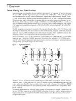
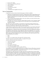
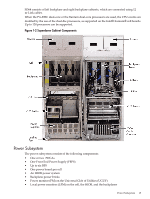
• the new CEC chipset • board changes including cell board • system backplane • I/O backplane • associated power boards • interconnect • a redundant, hot-swappable clock source Server Components A Superdome system consists of the following types of cabinet assemblies: • Minimum of one Superdome left-side cabinet. The Superdome cabinet contains the processors, the memory, and the core devices of the system. They also house the system's PCI cards. Systems can include both left and right cabinet assemblies containing a left or right backplane (SD64) respectively. • One or more HP Rack System/E cabinets. These rack cabinets are used to hold the system peripheral devices such as disk drives. • Optionally, one or more I/O expansion cabinets (Rack System/E). An I/O expansion cabinet is required when a customer requires more PCI cards than can be accommodated in the Superdome cabinets. The width of the cabinet assemblies accommodates moving them through standard-sized doorways. The intake air to the main (cell) card cage is filtered. This air filter is removable for cleaning and replacement while the system is fully operational. A status display is located on the outside of the front and rear doors of each cabinet. This feature enables you to determine the basic status of each cabinet without opening any cabinet doors. The Superdome is a cell-based system. Cells communicate with others utilizing the crossbar on the backplane. Every cell has its own I/O interface, which can be connected to one 12-slot I/O card cage using two System Bus Adapter (SBA) link cables. Not all SBA links are connected by default, due to a physical limitation of four I/O card cages per cabinet or node. In addition to these components, each system consists of a power subsystem and a utility subsystem. Three types of Superdome are available: • SD16 • SD32 • SD64, a two-cabinet system with single-CPU cell board sockets The SD## represents the maximum number of available CPU sockets. An SD16 contains the following components: • Up to four cell boards • Four I/O card cages • Five I/O fans • Four system cooling fans • Four bulk power supplies (BPS) • Two power distribution control assemblies (PDCA) Two backplane N+1 power supplies provide power to the SD16. The four cell boards are connected to one pair of crossbar chips (XBC). The backplane of an SD16 is the same as a backplane of an SD32. On the HUCB utility PCB is a switch set to TYPE= 1. An SD32 has up to eight cell boards. All eight cell boards are connected to two pairs of XBCs. The SD32 backplane is designed for a system upgrade to an SD64. On an SD32, four of the eight connectors use U-Turn cables. The U-Turn cables double the number of links and the bandwidth between the XBCs and are recommended to achieve best performance. An SD64 has up to 16 cell boards and requires two cabinets. All 16 cell boards are connected to four pairs of XBCs. The 18 Overview
-
 1
1 -
2
-
3
-
4
-
5
-
6
-
7
-
8
-
9
-
10
-
11
-
12
-
 13
13 -
 14
14 -
 15
15 -
 16
16 -
 17
17 -
 18
18 -
 19
19 -
 20
20 -
 21
21 -
 22
22 -
 23
23 -
24
-
25
-
26
-
27
-
28
-
29
-
30
-
31
-
32
-
33
-
34
-
35
-
36
-
37
-
38
-
39
-
40
-
41
-
42
-
43
-
44
-
45
-
46
-
47
-
48
-
49
-
50
-
51
-
52
-
53
-
54
-
55
-
56
-
57
-
58
-
59
-
60
-
61
-
62
-
63
-
64
-
65
-
66
-
67
-
68
-
69
-
70
-
71
-
72
-
73
-
74
-
75
-
76
-
77
-
78
-
79
-
80
-
81
-
82
-
83
-
84
-
85
-
86
-
87
-
88
-
89
-
90
-
91
-
92
-
93
-
94
-
95
-
96
-
97
-
98
-
99
-
100
-
101
-
102
-
103
-
104
-
105
-
106
-
107
-
108
-
109
-
110
-
111
-
112
-
113
-
114
-
115
-
116
-
117
-
118
-
119
-
120
-
121
-
122
-
123
-
124
-
125
-
126
-
127
-
128
-
129
-
130
-
131
-
132
-
133
-
134
-
135
-
136
-
137
-
138
-
139
-
140
-
141
-
142
-
143
-
144
-
145
-
146
-
147
-
148
-
149
-
150
-
151
-
152
-
153
-
154
-
155
-
156
-
157
-
158
-
159
-
160
-
161
-
162
-
163
-
164
-
165
-
166
-
167
-
168
-
169
-
170
-
171
-
172
-
173
-
174
-
175
-
176
-
177
-
178
-
179
-
180
-
181
-
182
-
183
-
184
-
185
-
186
-
187
-
188
-
189
-
190
-
191
-
192
-
193
-
194
-
195
-
196
-
197
-
198
-
199
-
200
 |
 |