HP Superdome SX2000 User Service Guide, Seventh Edition - HP Integrity Superdo - Page 40
PCI Slots, Mixed PCI-X and PCI Express I/O Chassis
 |
View all HP Superdome SX2000 manuals
Add to My Manuals
Save this manual to your list of manuals |
Page 40 highlights
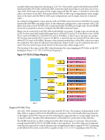
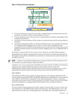
Cards that allow only 5 V signaling are not supported; PCI connector keying prevents insertion of such cards. Each LBA has control and monitor signals for use with a PCI hot-swap chip. It also converts PCI interrupts into interrupt transactions which are fed back to the CPUs. PCI Slots For maximum performance and availability, each PCI slot is sourced by its own LBA chip and is supported by its own portion of a hot-plug controller. All slots are designed to Revision 2.2 of the PCI specification and Revision 2.0a of the PCI-X specification and can support full size 64-bit cards with the exceptions noted below. Shorter or smaller cards are also supported, as are 32-bit cards. Slot 0 support for the core I/O card is removed on the SIOBP. SIOBP PCI slot support of VAUX3.3 and PME is not be supported. SMBus is supported in hardware through two I2C Muxes. Firmware can configure the muxes to enable communication to any of the 12 PCI slots. JTAG is not supported for PCI slots. Each device on a PCI bus is assigned a physical device number. On the past HIOB, the slot was configured as device 0. However, the PCI-X specification requires that the host bridge to be device 0. So for SIOBP the slot is configured as device 1. The SIOBP's ten outermost slots support only 3.3 V signaling (PCI or PCI-X Mode 1). The two innermost slots support either 3.3 V or 1.5 V (PCI-X Mode 2) signaling. All SIOBP PCI connectors physically prevent 5 V signaling cards from being installed. Mixed PCI-X and PCI Express I/O Chassis The 12-slot mixed PCI-X/PCI Express (PCIe) I/O chassis was introduced for the sx2000 Superdome with the two new dual-core Intel ® Itanium® processors and is heavily leveraged from the 12-slot PCI-X I/O chassis. The primary change replaces six of the LBAs with a new LBA ASIC to provide six PCI Express 1.1 compliant slots. The PCI-X/PCIe I/O chassis is only supported for Intel ® Itanium® dual-core processors. The new LBA provides an 8-lane (x8) Root Port compliant with the PCIe 1.1 specification. The six corresponding slots are compatible with PCIe cards with x8 or smaller edge connectors. PCIe slots are not compatible with PCI or PCI-X cards. Physical keying prevents installation of PCI or PCI-X cards into PCIe slots, or PCIe cards into PCI-X slots. The new PCIe I/O backplane board is a respin of the SIOBP3, with six of the LBA ASICs replaced with new PCIe LBA ASICs. These new LBA ASICs populate slots 2, 3, 4, 5, 6, and 7. All other slots contain PCI LBA ASICs. Slot 2 is a dual-thin rope; slots 3, 4, and 7 are fat-ropes and slots 5 and 6 are dual-fat ropes. All slots are hot-pluggable (Figure 1-12 "PCIe I/O Rope Mapping"). The new AIOBP I/O backplane uses most of the same mechanical components as the SIOBP. The differences are the PCIe connector, and the card extractor hardware. A PCI-X I/O chassis consists of four printed circuit assemblies; the PCI-X I/O backplane, the PCI-X I/O power board, the PCI-X I/O power transfer board, and the doorbell board plus the necessary mechanical components required to support 12 PCI card slots. 40 Overview
-
 1
1 -
2
-
3
-
4
-
5
-
6
-
7
-
8
-
9
-
10
-
11
-
12
-
13
-
14
-
15
-
16
-
17
-
18
-
19
-
20
-
21
-
22
-
23
-
24
-
25
-
26
-
27
-
28
-
29
-
30
-
31
-
32
-
33
-
34
-
 35
35 -
 36
36 -
 37
37 -
 38
38 -
 39
39 -
 40
40 -
 41
41 -
 42
42 -
 43
43 -
 44
44 -
 45
45 -
46
-
47
-
48
-
49
-
50
-
51
-
52
-
53
-
54
-
55
-
56
-
57
-
58
-
59
-
60
-
61
-
62
-
63
-
64
-
65
-
66
-
67
-
68
-
69
-
70
-
71
-
72
-
73
-
74
-
75
-
76
-
77
-
78
-
79
-
80
-
81
-
82
-
83
-
84
-
85
-
86
-
87
-
88
-
89
-
90
-
91
-
92
-
93
-
94
-
95
-
96
-
97
-
98
-
99
-
100
-
101
-
102
-
103
-
104
-
105
-
106
-
107
-
108
-
109
-
110
-
111
-
112
-
113
-
114
-
115
-
116
-
117
-
118
-
119
-
120
-
121
-
122
-
123
-
124
-
125
-
126
-
127
-
128
-
129
-
130
-
131
-
132
-
133
-
134
-
135
-
136
-
137
-
138
-
139
-
140
-
141
-
142
-
143
-
144
-
145
-
146
-
147
-
148
-
149
-
150
-
151
-
152
-
153
-
154
-
155
-
156
-
157
-
158
-
159
-
160
-
161
-
162
-
163
-
164
-
165
-
166
-
167
-
168
-
169
-
170
-
171
-
172
-
173
-
174
-
175
-
176
-
177
-
178
-
179
-
180
-
181
-
182
-
183
-
184
-
185
-
186
-
187
-
188
-
189
-
190
-
191
-
192
-
193
-
194
-
195
-
196
-
197
-
198
-
199
-
200
 |
 |